Posts Tagged static system
Miscellaneous Tasks Again (1/19/13)
Posted by Ethan Jacoby in Aft Fuselage, Center Fuselage, Construction, Fuselage on January 19, 2013
3.0 Hours –
I worked on a few more miscellaneous things today. First, I finished prepping the lower baggage bulkhead, including primer and paint.
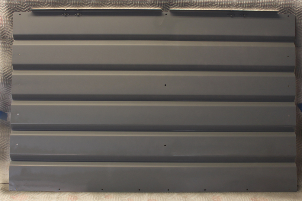
The lower baggage bulkhead primed and ready for paint.
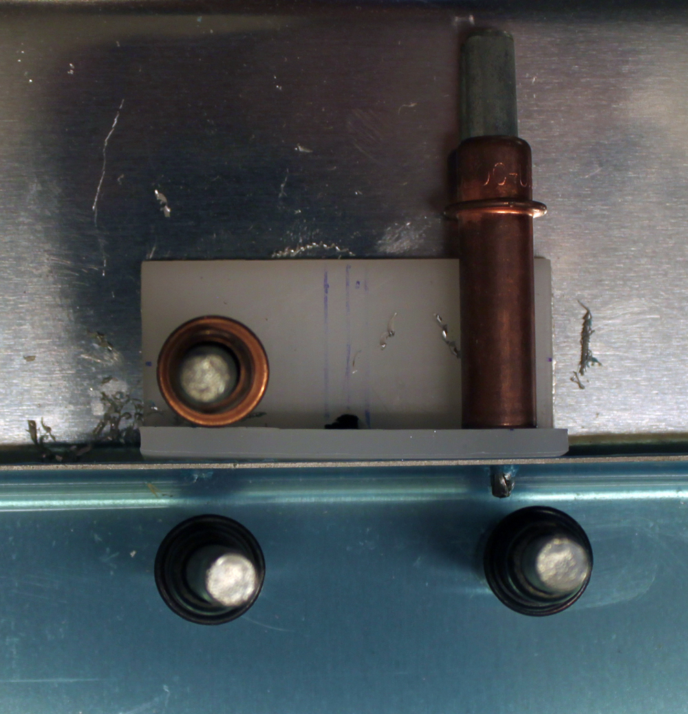
Next, I installed some tubing that connects the two static ports together. There’s no real need to install this now, other than to close the system, preventing debris from getting into the ports. I placed a tee connection on the left side. Eventually, a tube will run from the tee to wherever my ADAHRS (air data and compass module) are located. However, for now, I just attached a short length of tubing and closed off the end with some duct tape to make sure nothing could get in.
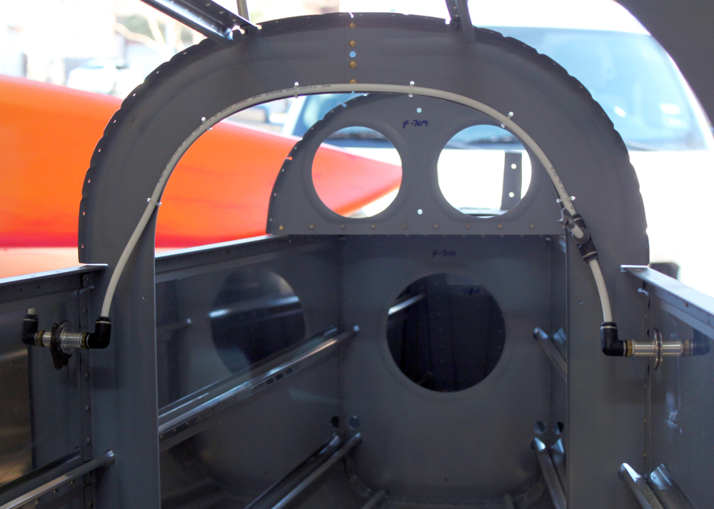
I installed the tubing that connects the static ports together. I did this now mainly to keep dirt, and other stuff, out of the system.
After taking a short break, I returned to the plane and prepped and painted the aft baggage covers. At this point, I think I want to paint anything going into the plane before it gets riveted. Along that line, I also decided to start getting the inside of the fuselage ready for paint. My plan is to paint everything from the F-706 bulkhead forward to where the sub-panel will be. That should cover everything that is visible. The floor forward of the F-704 won’t get painted though, as that will be covered with carpet. Similarly, I won’t paint anything that will later be covered by a floor board or access panel. Less paint equals less weight!
Baggage Bulkheads Started (1/12/13)
Posted by Ethan Jacoby in Aft Fuselage, Center Fuselage, Construction, Fuselage on January 12, 2013
4.8 Hours –
I was hoping that I would be able to get the static ports installed today, but FedEx didn’t show up with my order from Van’s in time. The order had a couple of small sealant kits in it, one of which was going to be used for installing the static ports. Instead, I only made it as far as drilling the holes for the ports in the side skins. Since I’m using the SafeAir static ports, I had to change the location slightly from that on the plans. My distance from the longeron rivet line remained the same at 2″ below the line, but I had to more the hole forward about a half-inch to accommodate the large flange on the SafeAir ports. Instead of 11/16ths forward of the bulkhead rivet line, I placed them at 1.25″ forward. Hopefully, this won’t introduce any error in my instruments that can’t be calibrated out. Once the locations were marked, I drilled and deburred 1/4″ holes. Installation of the ports will have to wait until I have the top skins off again.
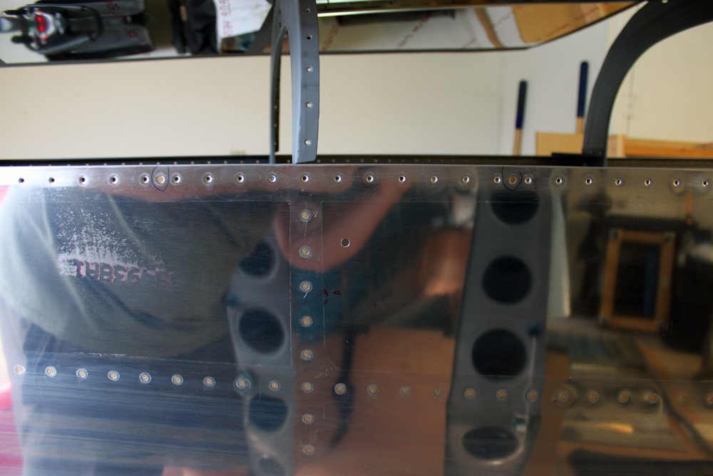
Since I’m using the SafeAir static ports, I had to move the port location slightly forward to accommodate the flange of the port. The center of the hole is 2″ down from the longeron rivet line, and 1.25″ forward of the vertical rivet line.
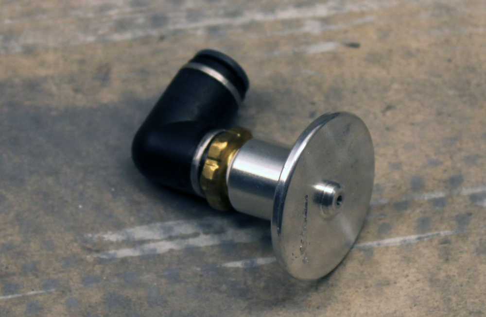
The SafeAir static ports with angled tubing adapter already attached. I wanted to install these today, but my pro-seal didn’t arrive from Van’s until after I had the top skins back on.
Since I wanted to keep working, rather than wait for my sealant, I clecoed the top skins back on. Right as I finished clecoing, FedEx showed up with the sealant. Since it took me about an hour to get the top skins back on, I decided to forge ahead, instead of taking the skins back off to install the static ports. On to the baggage bulkheads!
Before I could start working on the baggage bulkheads, I had to cleco in the aft baggage side covers and the baggage floors. With these in place, the baggage bulkhead could go in. The baggage bulkhead is split into upper and lower parts. The lower part has some pre-punched holes in it, and it can be clecoed to the corresponding holes on the lower section of the F-706 bulkhead. Once the lower part is clecoed, the sides can be match-drilled to the F-706 using the holes in the baggage bulkhead as guides. All of the holes are drilled for #8 screws. Eventually, the screws will be captured by nutplates installed on the aft side of the F-706 bulkhead.
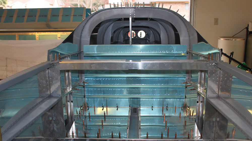
The lower baggage bulkhead is clecoed to the lower portion of the F-706 bulkhead, then the side are match-drilled.
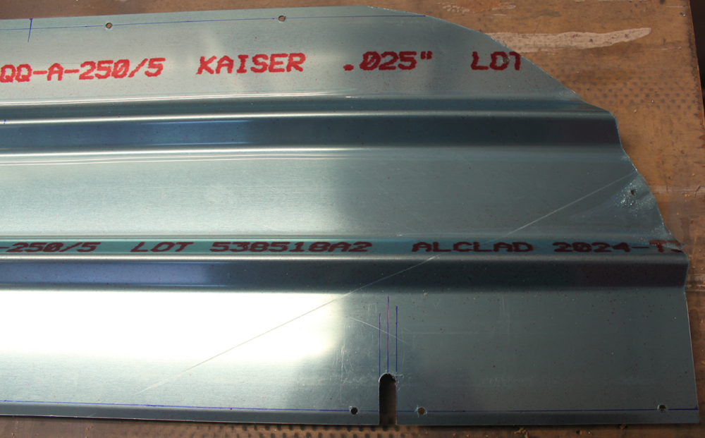
The top section of the baggage bulkhead is a bit more complicated. It comes as a rectangular pieces of corrugated aluminum sheet. The top of the sheet needs to have a couple of curves cut in it to match the curvature of the fuselage. Fortunately, the plans give very good details about the location and radii of the curves. The plans also give detailed measurements about where to drill additional holes for the screws that will attach the top section to the fuselage. Once everything was marked out, it was easy to cut the curves with my band saw. After cutting the top section, it was match-drilled to the F-706 bulkhead.
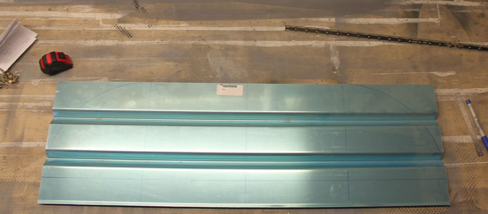
The upper baggage bulkhead has to have curves cut into the top. The plans are relatively clear about the location and radii of the curves. You probably can’t see my lines unless you click on the picture to zoom in.
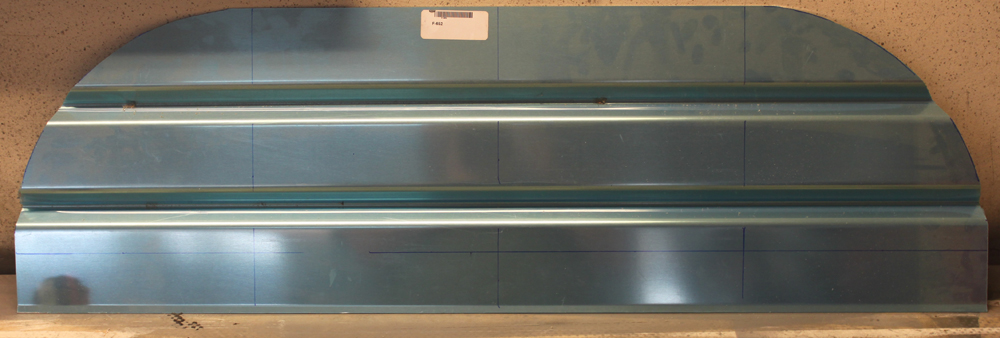
The upper baggage bulkhead with the curves cut. This was easy to do with my band saw.
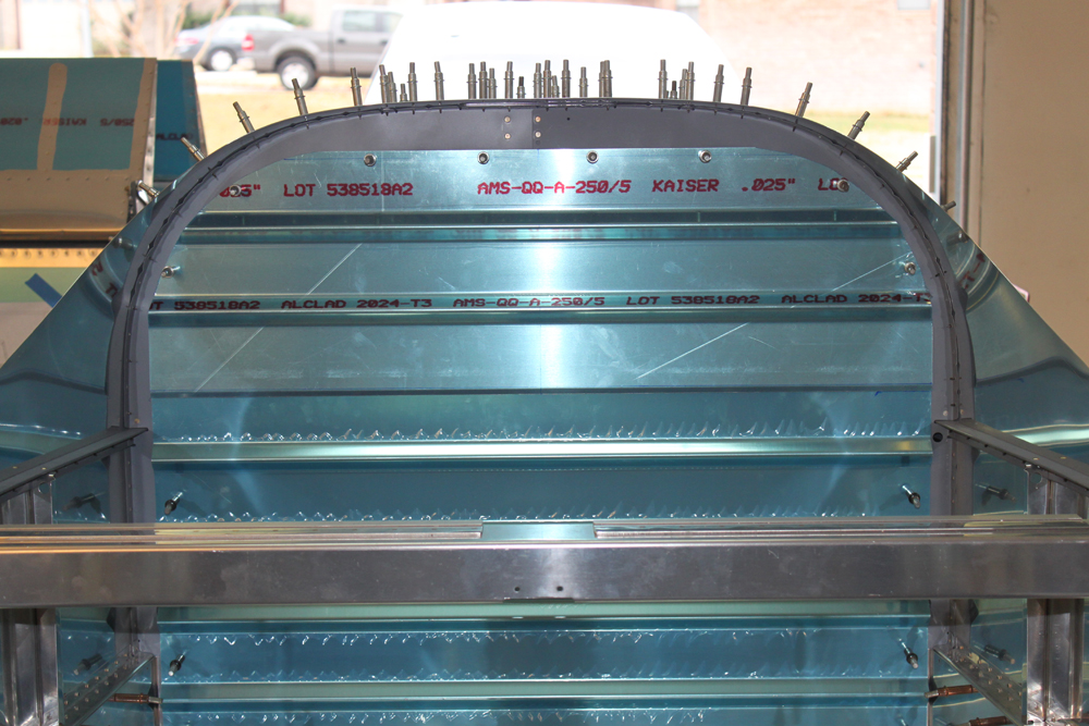
The upper baggage bulkhead is match-drilled to the F-706 bulkhead using hole location provided in the plans.
Next, I removed the top section of the bulkhead and cut two notches in it for the shoulder harness cable pass-throughs. Again, the plans had very clear locations for these, so they were simple to make.
Two notches have to be cut into the upper baggage bulkhead to act as pass-throughs for the cables that connect the shoulder harnesses to the airframe. Again, the plans had very clear details for the location of these notches.
Finally, I fabricated the wear blocks for the shoulder harness cable pass-throughs. These are just pieces of plastic that prevent the shoulder harness cables from rubbing on the aluminum bulkhead. The hardest part about making these was finding the stock material. Eventually, I discovered it in a small bag inside the bag containing the shoulder harness cables (a logical place that should have been my starting point). Of course, this bag was buried on the bottom shelf of my workbench under several other bags and coils of tubing.
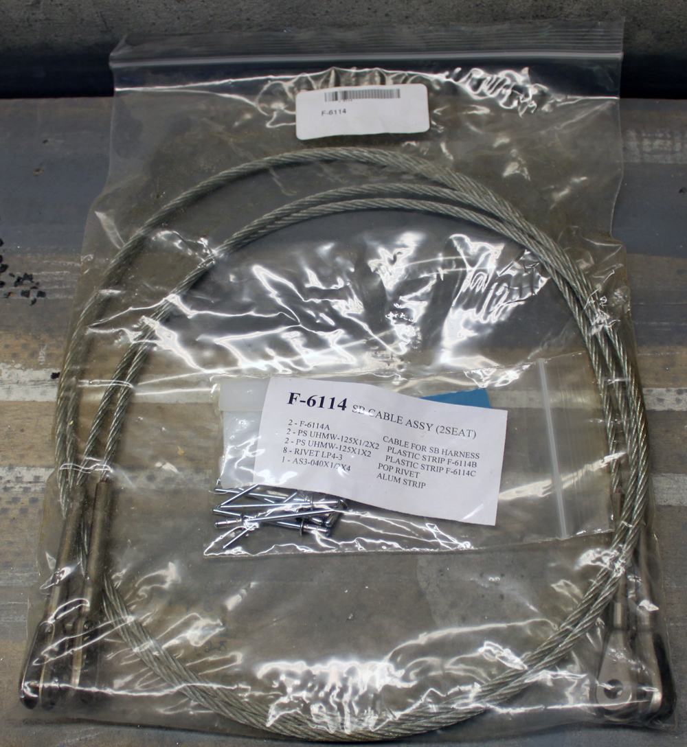
It took me awhile to find the parts for the wear blocks. They were in a small bag inside the seat belt cable bag, on the bottom shelf of my workbench, buried under a few other parts bags.
Once the parts were located, I made quick work of the fabrication. Several aluminum washers have to be made to give so that the rivets used to install the wear blocks will have better “grab” by having aluminum on both side instead of plastic. Rather than making aluminum washers, I’m going to use some aluminum rivet washers that I had purchased previously. Why do extra work when something you already have will work and look better! Two holes had to be drilled in each of the plastic blocks, and the larger blocks also had to have notches cut in them. Once all the parts were ready, I match-drilled them to the baggage bulkheads.
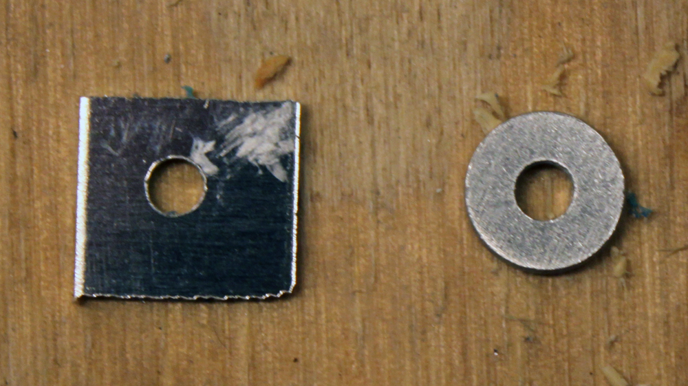
The wear block require 8 aluminum washers to be made from a strip of aluminum. I made them only to realize that I had some actual aluminum washers that would be perfect. It’s pretty obvious which one was made by me and which was made by a factory…I think I’ll use the factory-made washers!
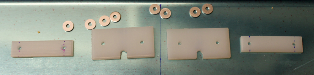
The completed wear block parts.
The wear blocks as seen from the aft side of the baggage bulkhead.
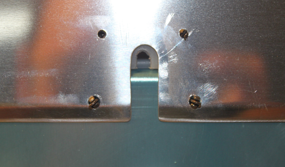
The wear blocks as seen from the font of the baggage bulkhead. At some point, these will be permanently installed with LP4-3 blind rivets.
F-706, F-707, and F-708 Bulkheads Started (1/5/12)
Posted by Ethan Jacoby in Bulkheads, Construction, Fuselage on January 5, 2012
3.0 Hours –
I couldn’t resist drilling the F-661EF flap actuator bearing blocks even though I don’t have the correct drill size yet. The closest drill I had to a #10 was a #12, so I chucked it into the drill press, clamped the block into place and drilled. The plastic was, of course, easy to drill, and I was actually surprised when I test fit a bolt and found that you really do have to go up in drill size when working with plastic. So, I’ll have to enlarge the hole once I get the #10 bit, but that’s easy. I’ll also wait until I have the other bit before drilling the second hole.

I started drilling the flap bearing blocks even though I don't have the right size bit. Clamped to the drill press with a piece of angle, the hole came out nice and straight.
Next, it was time to move on to some other bulkheads, so I had to spend some time rearranging the plans. I have so many large plans sheets now that rearranging them can take some time. It didn’t help that the drawings for the F-706, -707, and -708 bulkheads are split between two sheets.
After organizing the plans, I had figured out what parts I needed and set out on a search through the parts crate. After a bit of searching, I found everything I needed and got to work. The first thing I did was to locate and enlarge all the snap bushing holes for the rudder cables, wiring, and static system. Once these were all drilled, I started doing the finishing work on the bulkhead parts. These parts are in pretty rough shape out of the box. They are made from thin aluminum and they are severely warped in areas due to the way they are formed at the factory. Because of this, the bulkheads are going to take a lot of fluting to get them straight again. For today, I only finished the F-708 bulkhead components.

The raw parts for the F-706, 707, and 708 bulkheads are pretty rough looking...definitely going to have to prime these.

The bulkhead components are fairly warped from the bending process...time to do some fluting.

After fluting, the bulkheads look much better. There are still not perfect, but better.
Pitot-Static System
Posted by Ethan Jacoby in Preparation, Wings on May 14, 2010
As I wait for my wing kit to arrive, I’ve been purchasing items that will be needed to complete the wings. My most recent purchase is a Dynon pitot/AOA probe to complete my pitot-static system.

The Dynon pitot/AOA probe.
For the non-aviation geeks, the pitot-static system is a two part system that is used to measure airspeed and altitude. The system itself is very simple, consisting of ports on the outside of the plane which are connected to tubing. The tubing then runs to various instruments. The instruments translate changes in air pressure to useful information.
The pitot tube, mounted under the wing in this case, is used to measure airspeed. The static ports, consisting of two ports on the aft fuselage, are used to measure altitude and help correct the airspeed. Both the pitot and static ports allow outside air to enter the tubing they are attached to. The static ports are out of the slipstream and allow static air to enter. The pitot tube points forward. Air is forced into the tube as a result of the airplanes forward motion. The faster you go, the higher the pressure will be in the pitot system. The tubing for the pitot-static system is routed to various instruments which measure the pressure in the system and convert that to useful information such as airspeed and altitude. It may sound complicated, but it is actually a very simple system.
Van’s supplies aluminum tubing in the kit. This tubing is used to make all the pitot-static lines and the pitot tube. The static ports supplied in the kit are nothing more than a couple pop-rivet heads with tubing glued on to the back. While this works perfectly well, I decided to go another route. I’m using the Safeair1 pitot-static and AOA tubing kits, the Safeair1 pitot mast, the Safeair1 static ports, and a Dynon pitot/AOA tube.
The Safeair1 pitot, static, and AOA tubing is plastic tubing and push-on connectors. I feel this will be much easier to install than aluminum tubing and produce fewer leaks that have to be tracked down and fixed. The Safeair1 static ports are billet aluminum that has been milled to duplicate the shape of the Van’s pop-rivet port. They won’t work any better than the Van’s method, but they just look nicer.

The Safeair1 pitot-static tubing kit contains everything needed for an RV pitot-static system except for the pitot tube.

Safeair1 static ports. Left: tubing connection. Right: outside port.

The Safeair1 AOA kit contains more tubing and fittings for the AOA side of the pitot probe.
The only reason I’m using the Safeair1 pitot mast is because it is specifically made for use in an RV with the Dynon pitot/AOA tube. This alone should make it simple to install. The Dynon pitot/AOA is basically two tubes wrapped up in a very nice package. The upper port is the pitot port, while the lower port is the AOA. The AOA (or Angle of Attack) uses differential pressure between the two ports to measure the wing’s angle of attack (wing chord vs. relative wind). Simply put, it is a type of stall warning. However, AOA can also be used as a tool for landing. Navy pilots fly AOA, not airspeed, when they land on carriers.

The pitot/AOA probe mounts in the Safeair1 pitot mast. However, no instructions for how to do this...time to look up some other builders!

The pitot/AOA probe is simply two tubes angled away from each other and incased in a nice housing.

Interesting Stuff


