Posts Tagged F-706 bulkhead
Baggage Bulkheads Continued (1/13/13)
Posted by Ethan Jacoby in Center Fuselage, Construction, Fuselage on January 13, 2013
2.7 Hours –
The first thing I did today was to drill the platenuts to the F-706 bulkhead. As usual, I used the actual platenuts as my templates for the rivet spacing. I used screws and washer stacks to attach the platenuts to the front of the F-706, then I match-drilled the rivet holes. When they finally get riveted on, the platenuts will be moved to the aft side of the bulkhead.

A few of the platenuts that had to be installed on the F-706 bulkhead. I clecoed them to the front of the bulkhead for drilling the rivet holes, but they’ll eventually be on the aft side.
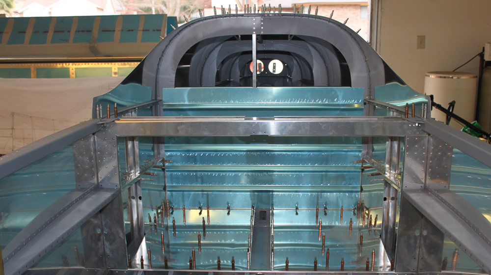
At this point, there was no longer a reason to have the top skins on the fuselage. They are only limiting access, so I took them off and placed them in the middle of my wing cradle for storage. They shouldn’t need to go back on the fuselage until I’m ready to rivet them. With the top skins off, it was much easier to do all the dimpling that needed to be done on the F-706 platenuts. I also removed the aft baggage covers and floors to do the final prep work on those.
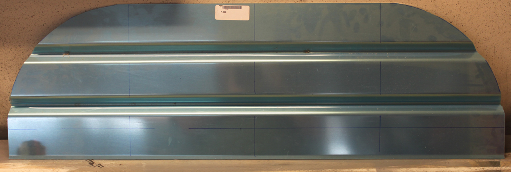
I decided today would be a good time to start painting some of the parts. The baggage bulkheads are both removable, so I thought I would start there. The upper baggage bulkhead was already finished, so all I had to do was scuff it with a Scotchbrite pad and clean it. Then, I gave it a coat of primer, let that flash dry, then gave it a coat of Rustoleum Hammered Silver. The Rustoleum paint is definitely easy to apply. No runs, and the hammered appearance likely covers up any of my smaller mistakes.

The upper baggage bulkhead after receiving a coat of primer (still wet).

The upper baggage bulkhead after being painted with some Rustoleum hammered silver. This stuff goes on easy!
In between paint steps, I started riveting the baggage platenuts to the F-706 bulkhead. For some reason, this was pretty slow going. I only managed to get through about half of the platenuts before calling it a day to go to a movie with my wife.
Baggage Bulkheads Started (1/12/13)
Posted by Ethan Jacoby in Aft Fuselage, Center Fuselage, Construction, Fuselage on January 12, 2013
4.8 Hours –
I was hoping that I would be able to get the static ports installed today, but FedEx didn’t show up with my order from Van’s in time. The order had a couple of small sealant kits in it, one of which was going to be used for installing the static ports. Instead, I only made it as far as drilling the holes for the ports in the side skins. Since I’m using the SafeAir static ports, I had to change the location slightly from that on the plans. My distance from the longeron rivet line remained the same at 2″ below the line, but I had to more the hole forward about a half-inch to accommodate the large flange on the SafeAir ports. Instead of 11/16ths forward of the bulkhead rivet line, I placed them at 1.25″ forward. Hopefully, this won’t introduce any error in my instruments that can’t be calibrated out. Once the locations were marked, I drilled and deburred 1/4″ holes. Installation of the ports will have to wait until I have the top skins off again.
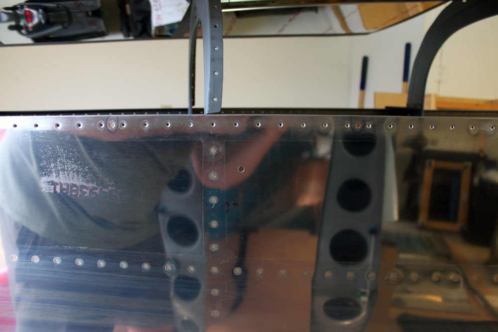
Since I’m using the SafeAir static ports, I had to move the port location slightly forward to accommodate the flange of the port. The center of the hole is 2″ down from the longeron rivet line, and 1.25″ forward of the vertical rivet line.
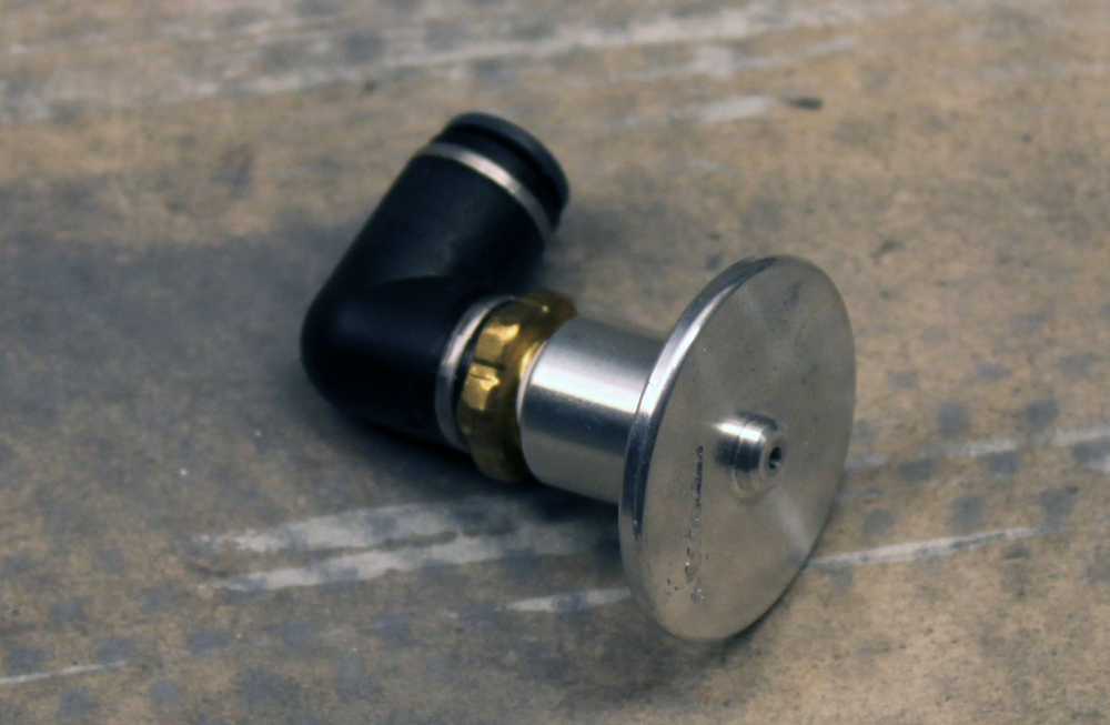
The SafeAir static ports with angled tubing adapter already attached. I wanted to install these today, but my pro-seal didn’t arrive from Van’s until after I had the top skins back on.
Since I wanted to keep working, rather than wait for my sealant, I clecoed the top skins back on. Right as I finished clecoing, FedEx showed up with the sealant. Since it took me about an hour to get the top skins back on, I decided to forge ahead, instead of taking the skins back off to install the static ports. On to the baggage bulkheads!
Before I could start working on the baggage bulkheads, I had to cleco in the aft baggage side covers and the baggage floors. With these in place, the baggage bulkhead could go in. The baggage bulkhead is split into upper and lower parts. The lower part has some pre-punched holes in it, and it can be clecoed to the corresponding holes on the lower section of the F-706 bulkhead. Once the lower part is clecoed, the sides can be match-drilled to the F-706 using the holes in the baggage bulkhead as guides. All of the holes are drilled for #8 screws. Eventually, the screws will be captured by nutplates installed on the aft side of the F-706 bulkhead.
The lower baggage bulkhead is clecoed to the lower portion of the F-706 bulkhead, then the side are match-drilled.
The top section of the baggage bulkhead is a bit more complicated. It comes as a rectangular pieces of corrugated aluminum sheet. The top of the sheet needs to have a couple of curves cut in it to match the curvature of the fuselage. Fortunately, the plans give very good details about the location and radii of the curves. The plans also give detailed measurements about where to drill additional holes for the screws that will attach the top section to the fuselage. Once everything was marked out, it was easy to cut the curves with my band saw. After cutting the top section, it was match-drilled to the F-706 bulkhead.
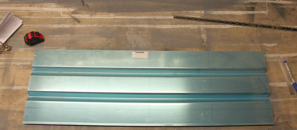
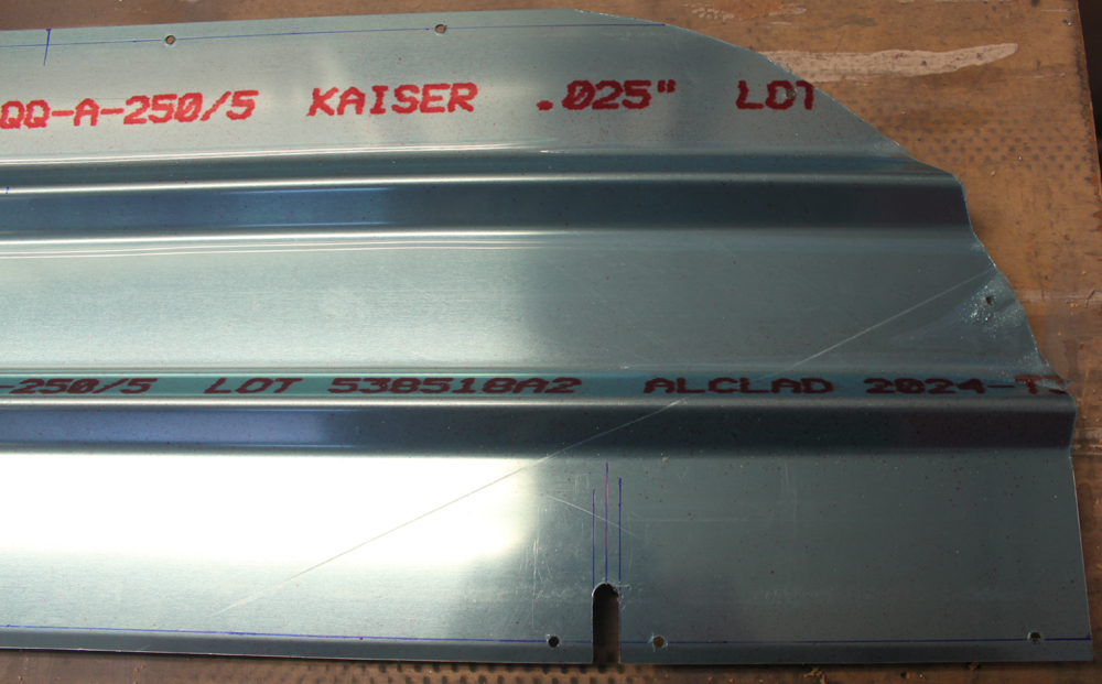
The upper baggage bulkhead has to have curves cut into the top. The plans are relatively clear about the location and radii of the curves. You probably can’t see my lines unless you click on the picture to zoom in.
The upper baggage bulkhead with the curves cut. This was easy to do with my band saw.
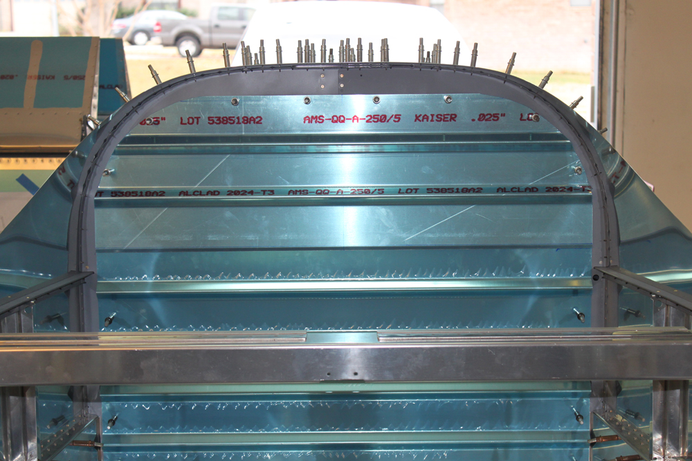
The upper baggage bulkhead is match-drilled to the F-706 bulkhead using hole location provided in the plans.
Next, I removed the top section of the bulkhead and cut two notches in it for the shoulder harness cable pass-throughs. Again, the plans had very clear locations for these, so they were simple to make.
Two notches have to be cut into the upper baggage bulkhead to act as pass-throughs for the cables that connect the shoulder harnesses to the airframe. Again, the plans had very clear details for the location of these notches.
Finally, I fabricated the wear blocks for the shoulder harness cable pass-throughs. These are just pieces of plastic that prevent the shoulder harness cables from rubbing on the aluminum bulkhead. The hardest part about making these was finding the stock material. Eventually, I discovered it in a small bag inside the bag containing the shoulder harness cables (a logical place that should have been my starting point). Of course, this bag was buried on the bottom shelf of my workbench under several other bags and coils of tubing.
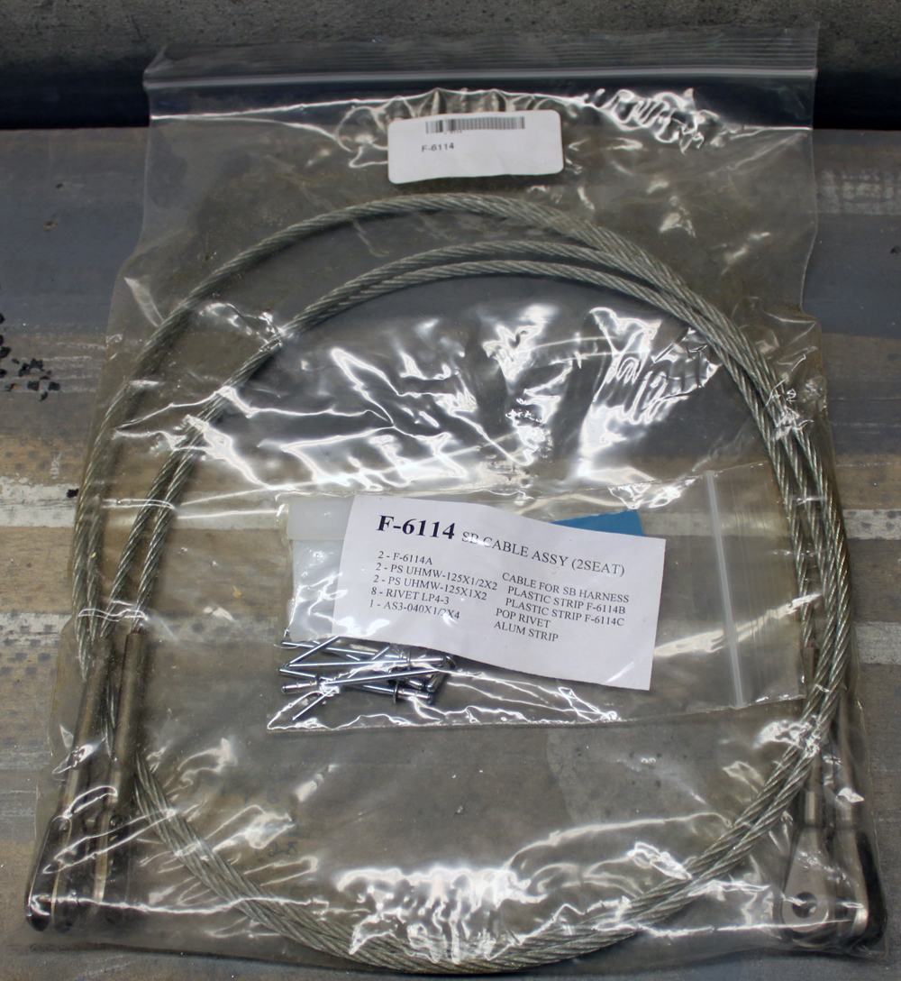
It took me awhile to find the parts for the wear blocks. They were in a small bag inside the seat belt cable bag, on the bottom shelf of my workbench, buried under a few other parts bags.
Once the parts were located, I made quick work of the fabrication. Several aluminum washers have to be made to give so that the rivets used to install the wear blocks will have better “grab” by having aluminum on both side instead of plastic. Rather than making aluminum washers, I’m going to use some aluminum rivet washers that I had purchased previously. Why do extra work when something you already have will work and look better! Two holes had to be drilled in each of the plastic blocks, and the larger blocks also had to have notches cut in them. Once all the parts were ready, I match-drilled them to the baggage bulkheads.
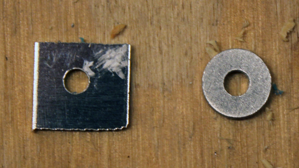
The wear block require 8 aluminum washers to be made from a strip of aluminum. I made them only to realize that I had some actual aluminum washers that would be perfect. It’s pretty obvious which one was made by me and which was made by a factory…I think I’ll use the factory-made washers!
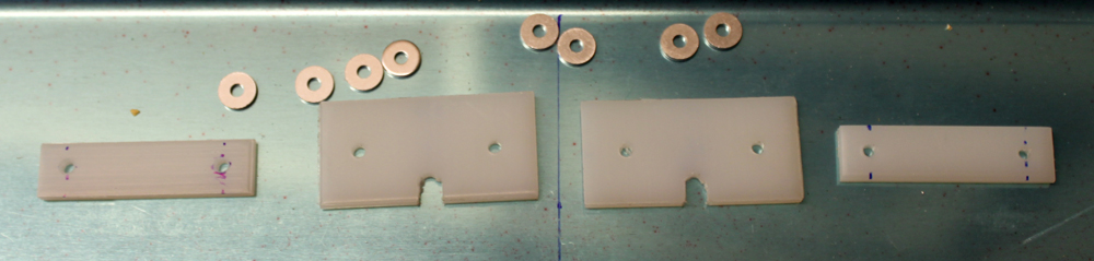
The completed wear block parts.
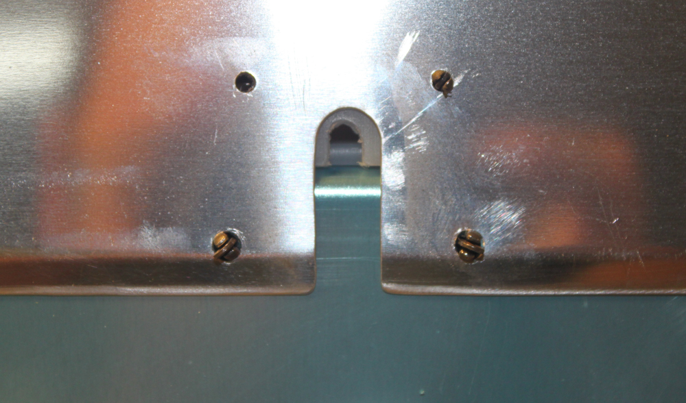
The wear blocks as seen from the aft side of the baggage bulkhead.
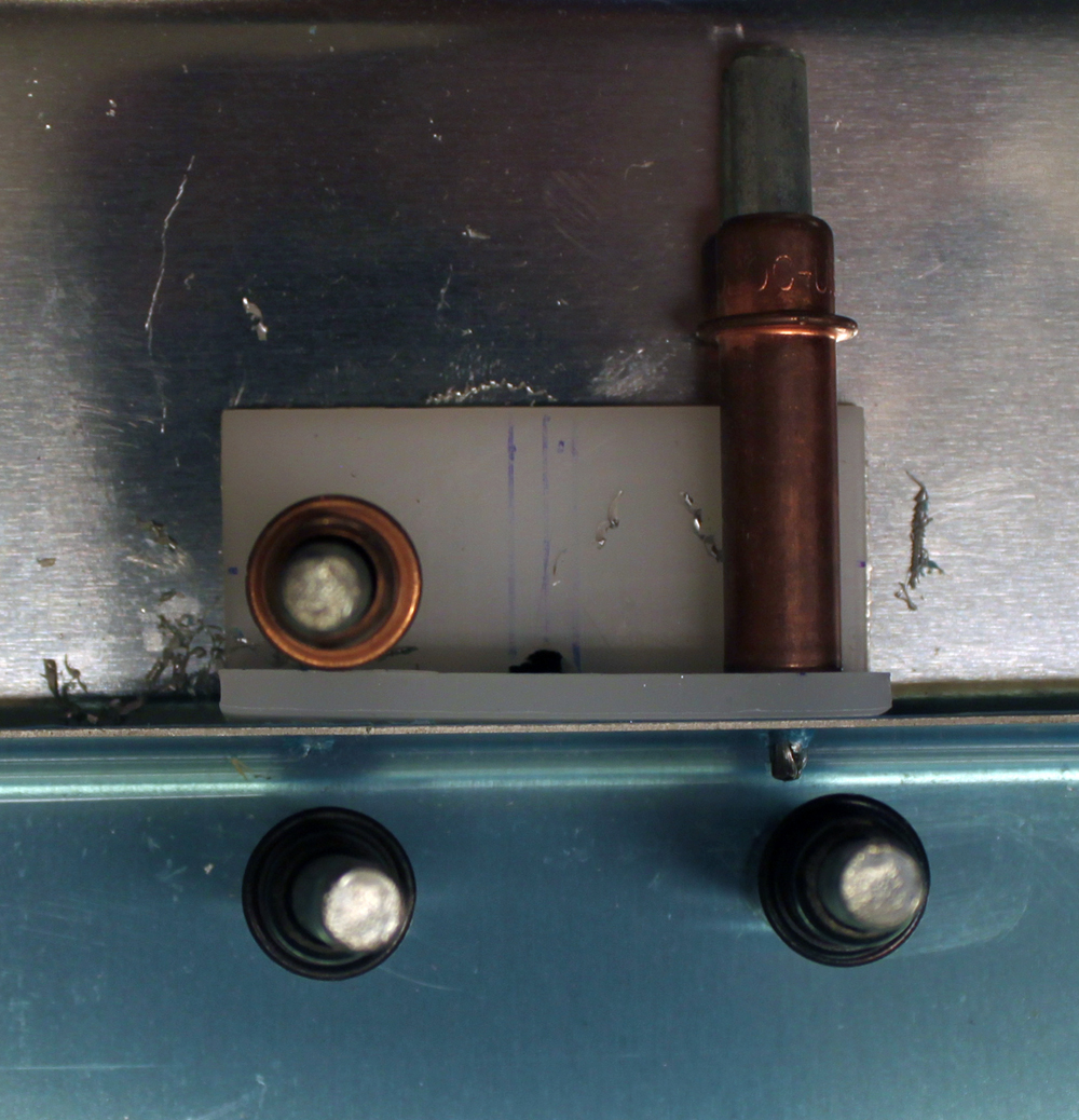
The wear blocks as seen from the font of the baggage bulkhead. At some point, these will be permanently installed with LP4-3 blind rivets.
Top Skins Continued (1/6/13)
Posted by Ethan Jacoby in Aft Fuselage, Construction, Fuselage on January 6, 2013
2.7 Hours –
I had a bit shorter day in the garage today, but I managed to get a good start on all the final prep for the top skins and associated parts.
I started by finishing the prep work on the j-stringers, F-787 stiffener, F-788 gusset, and the bulkheads. This was all deburring and dimpling, and every hole on these parts could be dimpled with my squeezer, so it took no time at all to finish.

The j-stringers, F-787 stiffener, and F-788 gusset, have all been finished and are ready for riveting.
Next, I riveted the F-787 stiffener assembly to the F-706 bulkhead using four flush rivets with the flush heads on the forward side of the bulkhead. The assembly does not get riveted to the F-707 bulkhead yet since the F-707B clip will block access to a couple of top skin rivets. As long at the stiffeners is only riveted to the F-706 bulkhead, the aft end, with the clip, can easily be moved around to gain access to the rivets.
At this point, I was ready to take a break for lunch. However, my rivet storage had been getting a little disorganized, and I decided it was finally time to re-arrange it. Fortunately, I keep all of my hardware in Stack-on storage bins. Each drawer holds one or two types of hardware, and I put labels on the front of each drawer. So, all I had to do was pull out all the rivet drawers, re-order them, and put them back in. I now have all my solid rivets grouped together and arranged by size (mostly). I also have all my blind rivets together and grouped by size. Rearranging bolts and washers will have to wait as it is a bigger task that will require moving thing around in the drawers themselves…not a task for today.

I spent a little time organizing hardware. For the longest time, I’ve been meaning to get all my solid rivets grouped into one area of my hardware bins and arranged by size.

I also organized all blind rivets into one area.
After lunch, I returned to the garage and started working on the aft top skin. I used by soldering iron to remove the blue vinyl along the rivet lines, deburred the holes and edges, dimpled with my c-frame, and primed the inner side of the rivet lines. The aft top skin is finished, and all I have left to prep is the forward top skin. I also looked into when to rivet the top skins. Basically, they can be riveted at anytime, but it is best to leave them unriveted as long as possible to make access to the aft fuselage easier. So, once I have the other skin prepped, I’ll just cleco them on and remove them as needed for access. I’ll rivet them when it seems to make the most sense.

Me, dimpling the aft top skin.
More Fuselage Riveting (11/10/12)
Posted by Ethan Jacoby in Center Fuselage, Construction, Fuselage on November 10, 2012
2.5 Hours –
I managed to get a little more riveting done on the fuselage.
The aft ends of the baggage ribs are now riveted to the F-706 bulkhead. Some of these could be squeezed, but the majority had to be bucked. Access was easy, but I hate having to use the offset rivet set.

The inboard baggage rib to F-706 rivets. These had to be bucked.

Some of the outboard baggage rib to F-706 rivets could be squeezed, while a few had to be bucked.
Next, I started riveting the baggage ribs. About halfway through the left side, I managed to spill my bin of 3-3.5 rivet all over the floor. Fortunately, they stayed in a relatively small area, and it was only one size of rivets, so it didn’t take me too long to clean up.

The left baggage rib and bulkhead are riveted.

Nothing ruins your day like spilled rivets! At least these stayed close together and it was just one size of rivet.
Fuselage Final Prep Day 8 (10/20/12)
Posted by Ethan Jacoby in Aft Fuselage, Center Fuselage, Construction, Fuselage on October 20, 2012
1.8 Hours –
More prep work today. The fuselage is now as taken apart as I can get it…everything that isn’t riveted together has been separated! Today, I deburred and dimpled the center fuselage section and the F-706 bulkhead assembly. I also started working on the longerons by deburring the inner side (the outer side will be countersunk). The aft fuselage still needs some deburring and dimpling, but that won’t take long. Countersinking the longerons is the last big task remaining.
Aft Fuselage Clecoed (2/11/12)
Posted by Ethan Jacoby in Aft Fuselage, Construction, Fuselage on February 11, 2012
2.5 Hours –
I started off by trimming the ends of the J-channels. On the lower four J-channels, both ends require trimming. However, I’m still not sure on the upper two, so those will have to wait. The actual trimming was completed by drilling a hole in the bend on the channel, enlarging the hole to the desired radius with a step-drill, and then finishing the cut with a Dremel and cut-off disc.
Once the J-channels were finished, I slid them back into place on the aft fuselage assembly. I then went to work clecoing the F-706 bulkhead to the aft fuselage. This took a little time since the F-706 assembly is a little bulky, and it took a little brute force to get things to line up at times.
With the F-706 in place at the front, I turned my attention to the rear and slid the F-710 bulkhead into place. The plans say to put the F-710 in last, but it is obvious that it would be a real pain to get the bulkhead in after the tail assembly is in place. With the F-710 loosely in place, I next started trying to cleco the F-779/F-711/F-712 assembly to the rest of the aft fuselage. At first, I couldn’t get the assembly to fit, but I quickly realized that the J-channels were interfering with the F-712 bulkhead. To fix this, I had to remove the tail assembly and trim a little more off the ends of the J-channels.
Once the J-channels were trimmed a bit better, it still took a little work to get the tail assembly to fit into place, but, eventually, I got it. I was able to cleco everything in the tail section except for one side of the F-711 bulkhead. The flanges of the bulkhead aren’t bent quite right. So, I’ll have to remove this part and re-bend the flanges so that they better match the angle of the fuselage side skin. Hopefully, this will take care of my fit problem.

The aft fuselage seen from the F-706 bulkhead looking back toward the tail.

A side view of the aft fuselage. The upper J-channels are just sitting on the top for storage...that's not their actually positioning.

The tail of the aft fuselage. The tail assembly is a real pain to get clecoed!

The flanges of the F-711 bulkhead still need some work. I'll have to remove the bulkhead and bend the flanges to better match the angle of the skin.
F-706 Finally Done, F-711 Started (1/19/12)
Posted by Ethan Jacoby in Bulkheads, Construction, Fuselage on January 19, 2012
1.8 Hours –
The primer on the F-706 sides was dry, so it was finally time to rivet them to the base and set the F-706 bulkhead aside. All of the rivets could be squeezed, but the base and sides are made from such thin aluminum that they were a bit of a challenge to rivet together. The challenges were mainly from the bulkhead being so light and flexible that it was hard to keep it in position. Oh well, the F-706 bulkhead has joined the many other partial assemblies in temporary storage. Hopefully, I’ll get to start putting the partial assemblies together at some point soon because I’m running out of storage room in the garage!

The F-706 bulkhead material is so thin that it is actually a little difficult to rivet. At least it can be set aside for a while now.
With the F-706 done, I wanted to wrap up the F-709 and F-710 bulkheads as well. Between the two bulkheads, there are only three parts. For tonight, I prepped and primed these parts. Tomorrow, I’ll rivet the F-710 angle to the bulkhead, and these parts will be finished (toss in my usual, “for now”).

There isn't much to the F-709 and F-710 bulkheads. Here, the parts are being primed.
On to the F-711 bulkhead. Van’s calls this a “double bulkhead.” Basically, it is two bulkheads riveted back to back. Since I actually knew where these parts were in the crate, it didn’t take me long to find everything I needed to get started. I clecoed the F-711A&B bulkheads together and then grabbed a length of AB4-187 x 1-1/4 bar stock and got to work fabricating the F-711C bars. The bars were simple to make…cut to length, draw a center line, drill three holes in each bar at the specified locations, and cut the outside top edge to a slight angle…easy.

The F-711 bars are fairly easy to make from the provided stock material. Just cut to length, drill a few holes, and add a taper.
Once made, the F-711C bars are clecoed and clamped to the F-711A&B bulkheads in order to drill the remaining holes. The centerline on the bars is visible through the holes in the bulkhead, and the bulkhead holes are used as the drill guides for match-drilling the bars. After the bars were fully drilled, I marked a section of each bulkhead half that needs to be trimmed away to make room for the elevator pushrod. However, I’ll leave the actual trimming for another day.

The F-711C bars are clamped to the F-711A&B bulkheads for drilling.

The blue centerline on the F-711C bars is visible through the holes in the F-711A&B bulkheads. The bulkhead holes are then used as guides for drilling.

The F-711C bars are drilled and the F-711A&B bulkheads are marked for trimming.
F-706 Again And Still Not Done (1/18/12)
Posted by Ethan Jacoby in Bulkheads, Construction, Fuselage on January 18, 2012
1.5 Hours –
If I had time for one long work session, I could easily wrap up the F-706 bulkhead. Unfortunately, working an hour or two every other day is really dragging out this section. Today, I managed to get the F-730 plate and the F-729 rib riveted to the F-706 base. Once this was riveted, I final-drilled the F-706 sides to the base. Once drilled, I deburred the holes and prepped the sides for priming. With the primer sprayed tonight, I should be able to rivet the sides to the base tomorrow.

The F-706 bulkhead base with the F-730 plate and F-729 rib riveted.

A close-up of the F-706 base structure so far. The scuffing around the upper holes is from my dimple dies...the camera flash really makes any marks pop-out from the shiny aluminum.

The F-706 sides are also being primed. I can't wait to be done with this bulkhead.
F-706, F-709 and F-710 Bulkhead Work (1/16/12)
Posted by Ethan Jacoby in Bulkheads, Construction, Fuselage on January 16, 2012
3.0 Hours –
Another day of bulkhead work…
My first task was to get some of the F-706 components ready for priming and riveting. However, before I could do that, I still had to match-drill, deburr, and dimple (as necessary), the F-706 base, F-730 plate, F-728 bellcrank channel, and F-729 bellcrank rib. Once that was done, I scuffed, cleaned and primed all of the angles and the F-706 base.

Another picture of priming. This is a few of the F-706 bulkhead parts.
Next, I started working on the F-709 and F-710 bulkheads. The F-709 was the easiest to complete since it is a one-piece bulkhead and it only needed to be deburred and fluted for now. The F-710 was a little more complicated, but not by much. The F-710 is also a one-piece bulkhead, but it also requires a small length of angle to be fabricated.
I would have made quick work of the F-710B angle if I could have found the correct angle stock. However, I spent well over a half-hour searching the garage for the 17 inch length of .125 x 1 x 1 angle stock that was listed on the inventory sheet. Since it was checked off the inventory, I knew it was hiding somewhere. When I was just about to give up, I finally found it buried deep inside the parts crate. For some reason, I didn’t put this piece of angle stock in the same place as all the other angle stock! Once the angle was located, making the F-710B was a piece of cake.

It took me longer to find the right angle stock than it did to make the actual part!

The F-709 and F-710 bulkheads after being straightened.
F-706 Bulkhead Work (1/15/12)
Posted by Ethan Jacoby in Bulkheads, Construction, Fuselage on January 15, 2012
3.0 Hours –
I still feel like I’m doing a lot of work on these bulkheads with little to show for it! Oh well, back at it today.
The first thing I did was to rivet together the, now primed, halves of the F-707 and F-708 bulkheads. One bulkhead had 6 rivets that could be set now and the other had 8. All of these rivets could be squeezed, so they took no time to install. At least I now have a couple finished bulkheads to show for all my work!

The F-707 and F-708 bulkheads are easy to rivet together.
I couldn’t delay the F-706 bulkhead any longer. This is the bulkhead with the really crappy looking parts. Specifically, the sides and bottom are a mess…very warped and ugly aluminum. After deburring the edges of the parts, I attacked them with my fluting pliers in an attempt to get them straight. This was a lot of work and they still aren’t as straight as I would like them to be. However the metal is so thin and flexible that I don’t think it will be a problem if I have to slightly “pull” them into place with clecoes through the skin when the time comes.
Next, there are three angles pieces that have to be fabricated out of .063 x 3/4 x 3/4 stock. The F-728B and F-729B angles are easy as they just have to be cut to the proper length. However, the F-729C angle takes a bit more work. For this part, the stock is cut to length, and then the plans state to close the angle very slightly to 88.5 degrees. To do this, I just clamped the angle in my vise and continued to close the vise jaws until the angle was closed very slightly. Easy enough.

The plans say to make the angle 88.5 degrees instead of 90...not much of a bend, but it was easy to squeeze closed in my vise.

After bending in my vise, the F-729C angle matches the plans perfectly.

All of the angles that need to be fabricated for the F-706 bulkhead have been made.
With all the angles made, I went ahead and match-drilled the two longer angles to the bellcrank support structure. The F-728B angle was drilled to the F-728A bellcrank channel, and the F-729B angle was drilled to the F-729A bellcrank rib.

The longer lengths of angle have to be match-drilled to the F-728A bellcrank channel and the F-729A bellcrank rib.
Finally, I clecoed the F-706 structure together for the first time. With the structure assembled, I could check the bend on my F-729C angle. It fit perfectly, so no more bending was needed. Next up, the structure will need to be final drilled, but that’s not going to happen today.

The F-706 bulkhead components clecoed together for the first time.

Interesting Stuff


