Posts Tagged aft fuselage
Empennage Fairing Finished (10/16/14)
Posted by Ethan Jacoby in Aft Fuselage, Construction, Empennage, Fuselage on October 16, 2014
5.0 Hours –
Once again, this post is actually a culmination of work I’ve been doing over the last two weeks. With the work I’ve been doing, on most days I don’t feel like I accomplished anything significant. However, after a couple of weeks, the empennage fairing is finished, which is definitely worth a post!
After a lot of sanding, I had a nice, smooth, and even surface on the empennage fairing, or at least I hoped this would be the case. Fiberglass parts can look great when they are bare, but as soon as you start spraying primer, the appearance can quickly go downhill as all the blemishes and pinholes suddenly appear. Fortunately, this was not the case when I primed the fairing this time. There were no pinholes, and the entire surface was nice and even. Happy with the finish, I decided I was done with the fiberglass work on the fairing and I could proceed with installation.

After a lot of sanding, I sprayed another layer of primer on the empennage fairing. This time, it looks great!

Another view of the empennage fairing.
Since I was busy priming, I also finished and primed the lower empennage fairings and the aft fuselage access doors. Once the primer dried on these, I re-installed them on the fuselage mainly to get them out-of-the-way for now.

I also primed the lower empennage fairings and the aft fuselage access panels.

I installed the aft access covers mainly to get them out-of-the-way.
Next, I installed the upper empennage fairing on the fuselage and final drilled all the holes for #6 screws. At this point, I should have taken a picture of everything put together because it looked pretty neat…but I didn’t, sorry. Instead, I started taking everything apart for the finishing work. The first thing was to countersink the holes in the upper empennage fairing for #6 screws and countersunk washers.

Since I was happy with the finish on the empennage fairing, I went ahead and drilled all the holes to full size and then countersunk them for #6 screws.
Then, I removed the vertical stabilizer and installed all the nutplates that will be used for the empennage fairing screws.

The vertical stabilizer was removed from the plane to make it easier to install all the empennage fairing nutplates.
Next, I installed the empennage fairing nutplates in the horizontal stabilizer. Once this was done, I took the horizontal stabilizer off the fuselage and stored it back on the wall. It will probably stay on the wall until it’s time to move to the airport for final assembly.

After installing all the empennage fairing nutplates on the horizontal stabilizer, I removed it from the fuselage and hung it back on the wall where it will stay until final assembly. I guess I should have taken a picture with the empennage fairing on prior to disassembly…whoops!
With the horizontal stabilizer removed, it was much easier to work on the lower empennage fairings. First, I was just going to rivet these to the fuselage, but then I decided to stick to the plans and use #6 screws to attach the fairings to the fuselage. All of the holes along the longerons were drilled and tapped, while the holes on the bulkhead required nutplates. A rubber seal will be placed between the fairings and the horizontal stabilizer during final assembly.

The lower empennage fairings were installed per plans by drilling/tapping the longerons for #6 screws.
Now that the empennage fairings are complete, my plan is to turn the fuselage back around in the garage and resume work on the canopy. In the meantime, I figured that the best place to store all of the empennage fairing parts was on the fuselage. If only I would have remembered to take a picture while the horizontal and vertical stabilizers were still attached. Oh well, you can use your imagination.

I figured the fuselage was the best place to store the empennage fairing. Too bad I forgot to take a picture of it with the horizontal and vertical stabilizers attached!

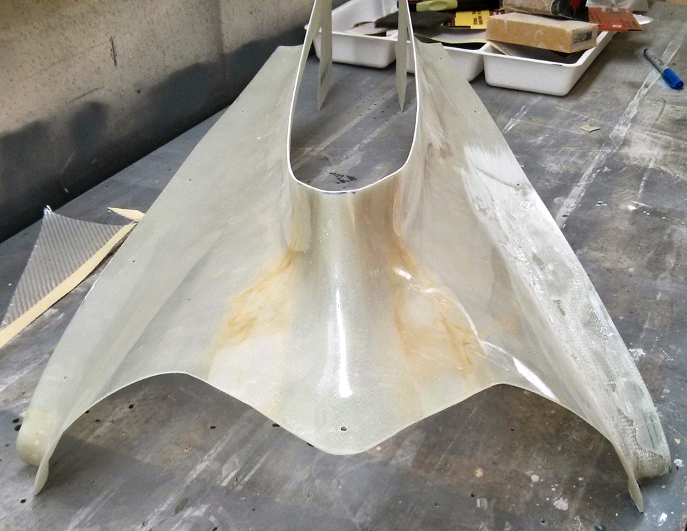
A front view of the completed empennage fairing. The fit is great!

Because I’m kind of proud of it, here’s one more view of the completed empennage fairing.
Still More Empennage Fairing Fiberglass Work (10/5/14)
Posted by Ethan Jacoby in Aft Fuselage, Construction, Empennage, Finishing, Fuselage on October 5, 2014
4.0 Hours –
Despite the posting date, this is actually work I’ve been doing since the last post. As I’ve said before, the problem with fiberglass is that you spend more time waiting for it cure than you actually spend doing any work.
After sanding down the initial layer of micro balloons, I still had a little depression at the front left edge of the fairing. So, I mixed up another batch of micro and spread it over the depressed area.

After sanding the first layer of micro balloons, I still had a slight depression near the front.

The second layer of micro applied.
After, once again letting the micro balloon mixture dry, I, once again, sanded it down. This time I was happy with the end result and replaced the fairing on the empennage to see how it looked. The fit on the left side is now much better than it was, and I haven’t even put any clecoes in yet. Now I just need to figure out how to drill these holes, because I can’t see through the micro like I could see through the fiberglass. Plus, my initial experiments with putting a light inside the tail didn’t seem to illuminate the holes either.

After sanding the second layer, the new section of the fairing looked great.

A closer view of the new glass.

The fit on the fuselage is good, even without any holes drilled.
After playing with a flashlight inside the tail area, I figured out that I just wasn’t going to be able to see the holes through the white micro balloon layer. So, I had to mark the horizontal stabilizer, do some careful measurements, and then drill blindly through the fairing while hoping that I’ll connect with the holes in the horizontal stabilizer. Fortunately, this worked well for all three holes that I had to re-drill in the fairing.
Once the left side of the fairing was re-drilled, I clecoed the fairing back in place, and I was happy to see a near perfect fit on the left side. The right side, as well as around the leading edge of the vertical stabilizer, still have minor gaps, but they aren’t bad enough to require laying new glass (I think). Instead, I decided to place a bead of flox (epoxy resin mixed with flocculated cotton) under the fairing where all the gaps were, then cleco the fairing on the fuselage. I’m hoping the flox will fill the gaps and, after a little sanding, leave a nice edge all around the front of the fairing.

To smooth out remaining gaps, I placed a bead of flox between the fairing and the fuselage.

You can see that the areas needing flox were all on the front edge of the fairing.

Rather than re-glassing the right front corner, I decided to fill the gap with flox and see how it turns out.
After letting the flox cure, I removed the fairing (not easy, but the front eventually released from the packing tape). I then sanded all the edges and applied a “filler” layer of epoxy over the entire surface of the fairing in attempt to fill any pinholes that are present. Unfortunately, I put my “filler” layer on a little too heavy and ended up with a lot of runs. So, I had to sand off the majority of the new epoxy.
Before spraying the first coat of primer on the fairing, I wanted to make sure all necessary holes for attaching the fairing to the plane were drilled. Once the primer is on, I won’t be able to see holes through the fiberglass, so it is better to at least drill pilot holes prior to priming. The only holes that were left to locate/drill were the screw holes that will be shared by the empennage fairing and the aft fuselage access covers. Locating and drilling these holes was a simple task, and I then moved on to priming the empennage fairing.

Before doing anything else with the empennage fairing, I drilled the access covers to the rear fuselage. Since the covers share holes withe fairing, I wanted to make sure all holes were drilled in the fairing before applying anything such as primer or filler that would make locating and drilling the holes more difficult.
Even though the first coat of primer was still wet, I could immediately see all of the flaws in the empennage fairing. There is a significant number of pinholes that will need to be filled, and there are also a few high spots, as well as curved sections that could use a little fine tuning. The high spots will just be sanded down, but the pinholes will need some filler plus sanding. At least all of the hard work is done, now it is just fine tuning any areas I’m not completely happy with.

After one coat of filler primer, the empennage fairing is a bit of a “Monet.” It looks great from a distance and in pictures, but when you look more closely, it is a bit of a mess (pinholes and high spots).

A side view of the empennage fairing after the first coat of primer was sprayed.
Finally, I added another layer of micro to fill some of the uneven areas and pinholes. The micro will need to cure overnight, then I can sand it down, add another coat of primer, and see where things stand.

Another layer of micro. After this cures, I’ll sand it smooth, add another coat of primer, and repeat.
More Empennage Fairing Fiberglass Work (9/21/14)
Posted by Ethan Jacoby in Aft Fuselage, Construction, Empennage, Fuselage on September 21, 2014
1.5 Hours –
Fiberglass work has, in my opinion, a few downsides. It’s messy, it makes you itch, it is more of an art than a science, and you have to spend more time letting things cure/dry than doing actual work. After 1.5 hours of work today, I’m back in the “letting it dry” phase.
Once I laid the new glass on the empennage fairing, I let the epoxy cure overnight and then I removed the fairing from the fuselage. I thought it might be hard to remove, but it actually popped right off thanks to the layer of clear packaging tape I placed between the fairing and the aluminum. After removing the fairing, I just let it sit on my workbench for a few days until I finally had some time to work on it again.
Today, I trimmed the new glass on the left side of the fairing so that the dimensions would match the right side. At least trimming glass is easy with a Dremel and cutoff wheel! Once trimmed, I used some very coarse sand paper to level off any high sports and smooth any rough edges. Overall, the new glass turned out relatively well. The thickness matched the rest of the fairing, and it seems to be solidly attached. The only problem area is near the front where a sort-of elongated dimple formed. To fix this, I mixed up some epoxy and added micro balloons until I had a consistency similar to peanut butter. I then slathered this mixture all over the newly glassed areas of the empennage fairing. The micro balloon mixture is very easy to sand, so putting it on nicely isn’t a concern…you just pile it on and then, after it cures, sand it down to the final shape you want. At least this is how I’m hoping it will work!
The new glass is on the right side in this picture (left side of plane). The rough shape turned out pretty good, but some filling is needed.

A side view of the new glass on the empennage fairing. It isn’t very obvious in the picture, but an indentation is present near the front that requires filling.
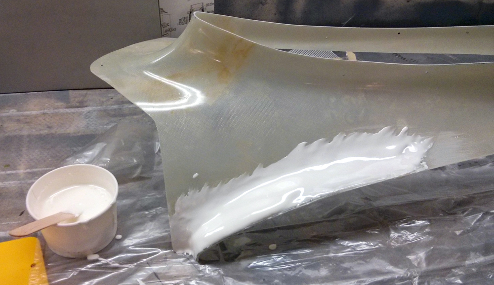
The epoxy/micro balloon mixture is put on fairly heavy, but it should be easy to sand into the final shape once it cures.
Empennage Fairing Fiberglass Work (9/14/14)
Posted by Ethan Jacoby in Aft Fuselage, Construction, Empennage, Finishing, Fuselage on September 14, 2014
1.5 Hours –
I know it has been four months since my last post, but I have been working on the plane occasionally. I’ve been doing little things here and there, but never enough to make it worth posting. Today, however, I decided to dive back in, head first, by doing some fiberglass work on the empennage fairing.
I’ve been working on trying to get the front left of the empennage fairing to lay flat with the horizontal stabilizer. For a large portion of the offending area, I was able to use a heat gun to gently warm and then re-shape the fairing. However, the leading edge of the fairing still sat about 1/4 inch above the stabilizer, and I knew there was no way it was going to stretch or bend any further. The only solutions were to fill the area or to cut it away and re-glass it. I opted to re-glass since filling might leave one side looking thicker than the other.
After cutting away the bad area of the empennage fairing, I started gathering all my fiberglass tools and materials. It has been a long time since I’ve done any fiberglass work, and I’ve never tried to glass a compound curve. I decided to use 6 layers of fiberglass (I can’t remember what type/weight I have, but I bought it because it would be suitable for just about everything on the RV), and I probably should have just laid out the material, added the resin, and then cut the strips I needed, but I decided to cut the strips first. No big deal, but it was probably a little harder to work with the epoxy soaked strips this way. However, it wasn’t long before I had the epoxy soaked glass laid out on the empennage fairing and covered with some peel-ply.

My West System epoxy is a few years old…hopefully it still works!

After cutting away the bad area of the empennage fairing, I put down six layers of glass. Wrapping it around the leading edge of the horizontal stabilizer was easier than I thought it would be.

Finally, a few strips of peel-ply went down to absorb some of the excess resin.
Later in the evening, I checked to see if the epoxy hardened. Since it did, I went ahead and removed the peel-ply and inspected my work. It isn’t the prettiest set up, but a little trimming and filling should make it work. Hopefully removing the fairing from the fuselage won’t be too difficult a task!

Later in the evening, I peeled the peel-ply, and this is what I had. Hopefully, it won’t be too hard to remove the fairing. Then, I’ll have a lot of trimming and filling to do.
Empennage Fairing Continued (5/18/14)
Posted by Ethan Jacoby in Aft Fuselage, Construction, Empennage, Fuselage on May 18, 2014
1.0 Hours –
Today, I continued working on the empennage fairing. First, I had to finish trimming the fairing. The dust created when trimming fiberglass parts is ridiculous. After trimming the fairing, all I wanted to do was take a shower!
Later in the day, I did a test fit of the fairing, and found that I needed to trim a bit more away from the area around the elevator horns. Once this was done, I was able to slide the fairing into position and check the fit. There were a couple of areas at the front that needed a little trimming, but the fit was descent. After making a couple more trims, I replaced the fairing and decided I wouldn’t be able to do much more without securing the fairing to the fuselage. So, I started drilling.

After trimming the empennage fairing, I positioned it for the initial fit.

A closer view of the left front. This is the biggest gap, but it isn’t visible from this angle.

The forward portion fits pretty well.
After drilling and clecoing the fairing to the fuselage, I was able to get a better idea about the problem areas. There is a pretty good gap on the left front over the horizontal stabilizer. Other than that, the fit is, surprisingly, problem free. The right side is just about perfect, and a little work with the heat gun should be all it needs. The left side will likely need more work. I’ll try the heat gun first, but the left side may need some additional fiberglass work.

After drilling the fairing to the fuselage and tail surfaces, the only major gap is on the front left of the fairing. I’m hoping I can fix this with a heat gun. If not, I’ll have to pull out the fiberglass supplies.

A closer view of the gap at the front left of the fairing.

The right side of the fairing fits almost perfectly. A little work with the heat gun should smooth out any problem areas on this side.

A closer view of the front right.
Empennage Fairing Started (5/17/14)
Posted by Ethan Jacoby in Aft Fuselage, Construction, Empennage, Fuselage on May 17, 2014
1.7 Hours –
It has been a busy couple of weeks, so I haven’t had any time to work on the plane. However, before removing the horizontal and vertical stabilizers for storage, I wanted to work on the empennage fairing. The fairing consists of three parts. The upper fairing is fiberglass, while the lower portions are aluminum.
First, the lower fairings have to be fit to the aft fuselage under the horizontal stabilizer. In order to fit these, some of the fairing has to be trimmed away (varies by airplane), and several rivets have to be drilled out of the aft fuselage. I’m not sure why there isn’t a note about leaving these holes empty when the fuselage is riveted, as drilling out rivets is never fun. However, after drilling out the rivets, it was relatively easy to install the fairings and trim them as needed. Although, I may need to trim them more once I’m ready to install the rubber gap seals. Eventually, the lower fairings will be installed with screws, but, for now, clecoes will do.

The lower empennage fairing has to be trimmed a bit before it can be installed under the horizontal stabilizer. It may need more trimming before adding the rubber gap-seal.

A closer view of the front end of the lower empennage fairing.
After the lower fairings were fit, I started trimming the upper, fiberglass fairing. The instructions for installing the fairings are almost non-existent, so I’m basically flying by the seat of my pants on this. There are score marks all around the fairing, which usually indicate initial trim points, so I’m following those lines and trimming the fairing using a Dremel with a cut-off disk. The trimming is pretty easy, but it kicks up a lot of fiberglass dust. Once the initial trimming is complete, I’ll be able to test fit the fairing on the plane and trim more as needed. After trimming about half of the fairing, I decided it was time to go take a shower!

I started trimming the fiberglass upper empennage fairing. There are score marks (marked blue so I can see them more easily while cutting) that I’m following for initial trimming…instructions are vague.
Vertical Stabilizer Installation Complete (4/26/14)
Posted by Ethan Jacoby in Aft Fuselage, Construction, Empennage, Fuselage, Vertical Stabilizer on April 26, 2014
1.0 Hours –
Today, I finished installing the vertical stabilizer by drilling holes for the three bolts that hold the lower portion of the vertical stabilizer’s aft spar to the fuselage and tailwheel mount. For the most part, this was a pretty simple task. However, there is always some hesitation when you are drilling through this much material and one of the major parts isn’t visible or easily measured. In this case, the aft flange of the tailwheel mount sits behind the fuselage bulkhead, and envisioning where it begins and ends is difficult. Fortunately, following the measurements in the plans worked for me.
Next up, I want to install the rudder, fit the lower rudder fairing, install the tail light, and install the main empennage fairing.

Three bolts connect the lower portion of the vertical stabilizer to the fuselage and tailwheel mount.
Empennage Installation Continued (4/25/14)
Posted by Ethan Jacoby in Aft Fuselage, Construction, Elevators, Empennage, Fuselage, Vertical Stabilizer on April 25, 2014
1.7 Hours –
The first thing I wanted to do was to get the elevator pushrods reconnected to the bellcrank in the fuselage. I struggled reaching these parts the other day, but then I realized that the forward top skin still hadn’t been riveted to the fuselage and could be removed to ease access. Once I took a few clecoes out, and could duck under the side of the skin, getting the bolts through the rod ends and bellcrank was a piece of cake.
After the pushrods were installed on the bellcrank, I reattached the aft pushrod to the elevators. With everything connected, I placed the bellcrank in the neutral position and then checked to see if the elevators were also neutral (in-trail). The elevators were slightly up, which meant the pushrod needed to be shortened. I removed the pushrod from the bellcrank, gave the rod end a couple twists and then reconnected everything. With this slight adjustment, the elevators and bellcrank were both perfectly neutralized. I then double checked that more than half of the threads on the rod ends were engaged (well over half on the aft rod end, and almost all on the forward), torqued the jam nuts on the pushrod and marked them with some torque seal. The pushrod should not need to be adjusted anymore (hopefully).

Both elevator pushrods are now attached to the bellcrank inside the fuselage. The length of the aft pushrod has been set, but the forward pushrod still need to be attached to the controls.
Next, I bolted and riveted the up elevator stop to the fuselage, and then riveted the F-781 plate to the forward spar of the vertical stabilizer. Fortunately, all of these rivets could be reached with my pneumatic squeezer. Once the elevator stop was in place, I checked to make sure it was the first thing the elevator horns hit. While the elevator horns hit both the up and down stops before contacting anything else, I still need to check the amount of elevator deflection and possible shorten the stops if the deflection isn’t adequate.
Finally, I re-installed the vertical stabilizer. Right now, the vertical stabilizer attaches with 6 bolts. Two bolts are through the aft spar and the up elevator stop, and four bolts are through the front spars of both the horizontal and vertical stabilizers. Now, all that is left for the vertical stabilizer installation is to drill the lower portion of the rear spar to the aft bulkhead of the fuselage and the tail wheel mount.

The F-781 plate was riveted to the forward spar of the vertical stabilizer. Then, the stabilizer was mounted on the fuselage.

The up elevator stop was riveted and bolted to the fuselage and vertical stabilizer. There is a washer on the between the stop and the vertical stabilizer on the left side to help with the offset of the stabilizer. I do need a longer bolt on that side though.

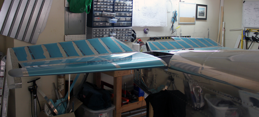
Everything except the rudder!

Looking more and more like an airplane!
Vertical Stabilizer Installation Started (4/20/14)
Posted by Ethan Jacoby in Aft Fuselage, Construction, Empennage, Fuselage, Vertical Stabilizer on April 20, 2014
4.0 Hours –
The goal for the day was to have the vertical stabilizer drilled to the fuselage. I came close to completing this, but I was sidetracked with other tasks that I thought would make installation of the vertical stabilizer easier.
First, I double checked the verticalness? verticality? of the vertical stabilizer. To do this, I measure from the upper most rudder hinge on the aft side of the vertical stabilizer to equivalent rivets on each side of the horizontal stabilizer. Since the distances were the same, the vertical stabilizer should be vertical.
Next, the F-712D up elevator stop is clamped to the vertical stabilizer’s aft spar and the aft deck of the fuselage, and drilled to the vertical stabilizer. I wasn’t happy with the F-712D stop that I made the other day, so I decided to make a new one. This time, I fabricated the part using a combination of measurements taken from my fuselage/vertical stabilizer and the plans. By doing this, my new F-712D was slightly larger, but it gave me more edge distance to play with. I figured I could cut the part down a bit after all the holes were drilled.

Once the vertical stabilizer is positioned, it can be drilled to the F-712D up elevator stop.

Last, the F-712D up elevator stop is drilled to the longerons.
Once the new F-712D was made and drilled to the vertical stabilizer and longerons, it was time to position the leading edge of the vertical stabilizer. To do this, the F-781 plate is clamped to the forward spars of both the horizontal and vertical stabilizers. Once clamped, the rudder hinge line on the aft spar of the vertical stabilizer is checked with a straight edge to ensure it is straight. There are multiple ways to fix the vertical stabilizer if the hinge row is not straight, but I didn’t have to worry about this as mine checked out OK with the forward spar of the vertical stabilizer clamped directly to the aft side of the F-781 plate.
Next, the leading edge of the vertical stabilizer needs to be offset from the centerline of the fuselage a 1/4 inch to the left. The point of this is to counteract the left turning tendencies of the airplane. I only had to make a slight adjustment to get the 1/4″ offset, and then I rechecked the rudder hinge line once more to ensure it was still straight. With everything checking out, I match-drilled the F-781 plate to both the horizontal and vertical stabilizers. I was able to easily drill all but the uppermost row of rivet holes on the F-781 with the vertical stabilizer on the fuselage. To get the upper row, I had to take the vertical stabilizer off and use an angle drill.

The leading edge of the vertical stabilizer is offset 1/4″ to the left of center in order to help counteract the planes left turning tendencies.

After the leading and trailing edges are positioned, the vertical stabilizer’s forward spar is drilled to the horizontal stabilizer and the F-781 plate.
Once the F-781 was drilled, I completed all the hole and edge finishing on both it and the F-712D up elevator stop. I also scuffed, cleaned and primed both of these parts.

The primed F-781 plate and F-712D up elevator stop.
Finally, I decided that I would work on the elevator pushrods so that I could lock in the pushrod lengths and then remove the elevators. With the elevators off I figured I would have much more room to work on the other tail parts (the elevator horns extend below the aft deck and take up a lot of access room). Since I was going to work on the pushrods, I figured I would get both the forward and aft push rods set at the same time. Getting the forward pushrod, which connects the control sticks to the elevator bellcrank, was a lot more work than I thought it would be because a whole lot of stuff had to be removed from the cabin/baggage area in order to get enough access to slide the pushrod into position. By the time I had the forward pushrod in position, I had enough and decided to call it a day.
More Empennage Installation (4/19/14)
Posted by Ethan Jacoby in Aft Fuselage, Construction, Elevators, Empennage, Fuselage, Horizontal Stabilizer, Vertical Stabilizer on April 19, 2014
3.5 Hours –
Today, I continued working on the empennage installation. However, before I could do any more work on the plane, I had to gather all the parts. For the empennage, this meant climbing into the attic. Normally, this is an easy task, but with a garage full of large airplane parts, lowering the attic ladder isn’t always possible without significant rearrangement. Fortunately, I was able to push the tail of the fuselage far enough over for the ladder to come down. Then, it was just a matter of handing the tail pieces down to my wife one at a time. Surprisingly, these parts, which have been in the attic for years, had very little dust built-up on them, and absolutely no corrosion that I could see.
The first task was to install the elevators on the horizontal stabilizer and drill the elevator horns for the push rod bolt. To do this, the horizontal stabilizer was placed upside down on my workbench. The elevators were then installed with assembly pins and clamped in the “in-trail” position. The elevator horns are not a matched set, so there is a little variance between parts. Most builders do not have horns that are perfectly aligned. Although my horns were close, the right horn is about 1/4″ aft of the left horn. Once the aft horn is identified, it is drilled in the appropriate location with a #30 pilot hole. Then, I made a spacer/drill guide for between the horns using a block of wood. This spacer has a #30 hole drilled through it using the drill press to ensure that the hole is perpendicular to the block. The spacer is then inserted between the horns and used to guide the drill for cutting the hole in the opposite elevator horn. Once both horns have a pilot hole, the holes are enlarged for an AN3 bolt.
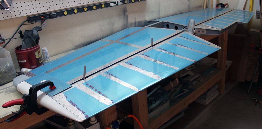
On the workbench, the elevators are temporarily installed on the horizontal stabilizer and clamped in the “in-trail” position.
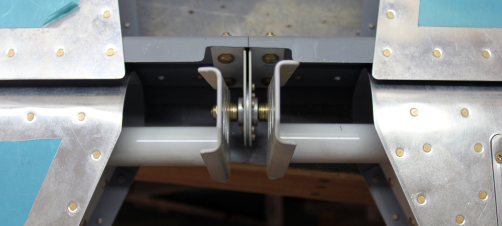
The elevator horns aren’t a matched set, so one is usually aft of the other, and this must be accounted for when drilling the hole where the push-rod will attach. My right elevator horn is slightly aft (left in this picture since the whole assembly is upside down).

A wood block is used to make sure that the holes in the elevator horns are perfectly aligned. The wood block has a #30 hole through it that was made with the drill press to ensure straightness.
The aft (right) horn is drilled to #30 first. Then the block is used to align the drill for forward (left) horn. Once the pilot holes are drilled, the block is removed and the holes are enlarged for an AN3 bolt.
Next, the elevators were removed from the horizontal stabilizer so I could move the parts to the fuselage. Once the horizontal stabilizer was on the fuselage, the elevators were reattached, and I was able to bolt the push rod to both elevators. With the push rod attached, I checked to make sure the elevators were aligned with each other and moved freely in both directions. With the lightest touch, I could easily move the elevators, and there was no binding of any kind. Needless to say, I had to play with elevators for a few minutes!
Once the elevator horns were drilled, the whole assembly was installed on the fuselage and the elevators were connect to the pushrod. Here they are, moving together, in the up position.

And, of course, here they are in the down position. Ignore my finger…without holding them, they want to go back to neutral or up.
Once I finished playing with the elevators, I moved on to the vertical stabilizer. The first thing is to cut 5/8″ from the bottom of the forward spar of the vertical stabilizer. I’m not sure why Van’s doesn’t have you do this before assembling the vertical stabilizer since it would be easier at that time, but it was still relatively easy to do this using my Dremel and cut-off disc. Next, I clamped the F-781 attach plate to the forward spar of the horizontal stabilizer and then clamped the vertical stabilizer to the fuselage. At this point, the vertical stabilizer has to be positioned so that it is exactly vertical and the leading edge is 1/4″ left of center (to offset left turning tendency). I took some measurements and re-positioned the vertical stabilizer to where I think the fit is correct, but I want to take a break and re-measure before doing any actual drilling. I’ll return to this tomorrow.
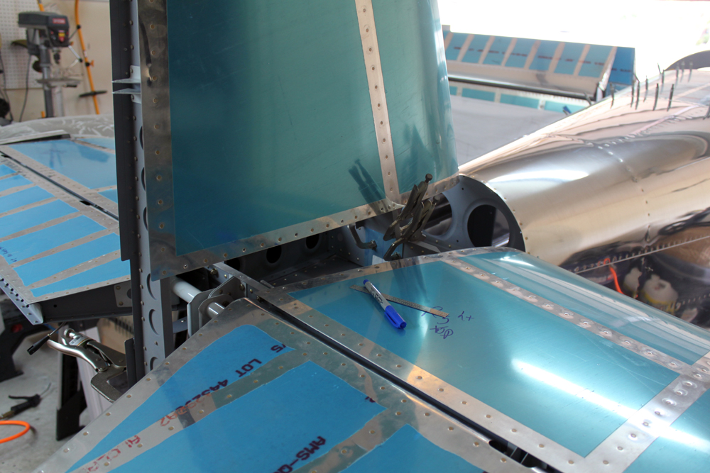
The vertical stabilizer is clamped to the horizontal stabilizer’s forward spar and to the rear bulkhead of the fuselage.
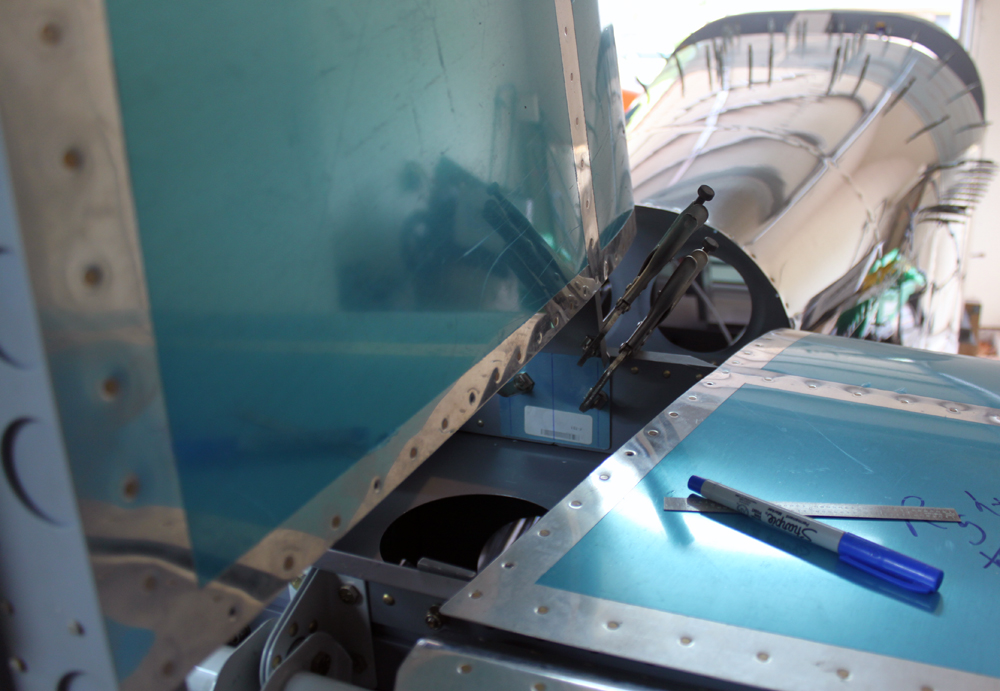
A closer view of how the vertical stabilizer is clamped to the horizontal stabilizer’s forward spar.
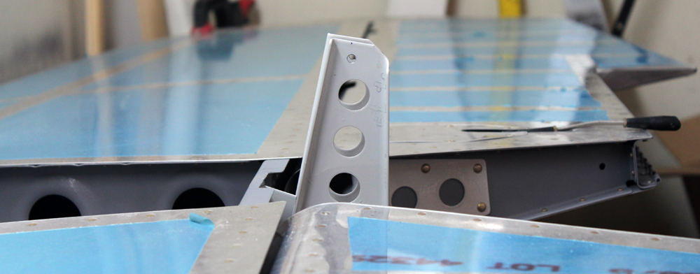
In the meantime, I started fabricating the F-712D up elevator stop. This part is fashioned from some stock angle, and I managed to get the rough cuts done, but it still needs a lot of finishing work. However, since this is the first part to get drilled to the vertical stabilizer, it will be at the top of my priority list.
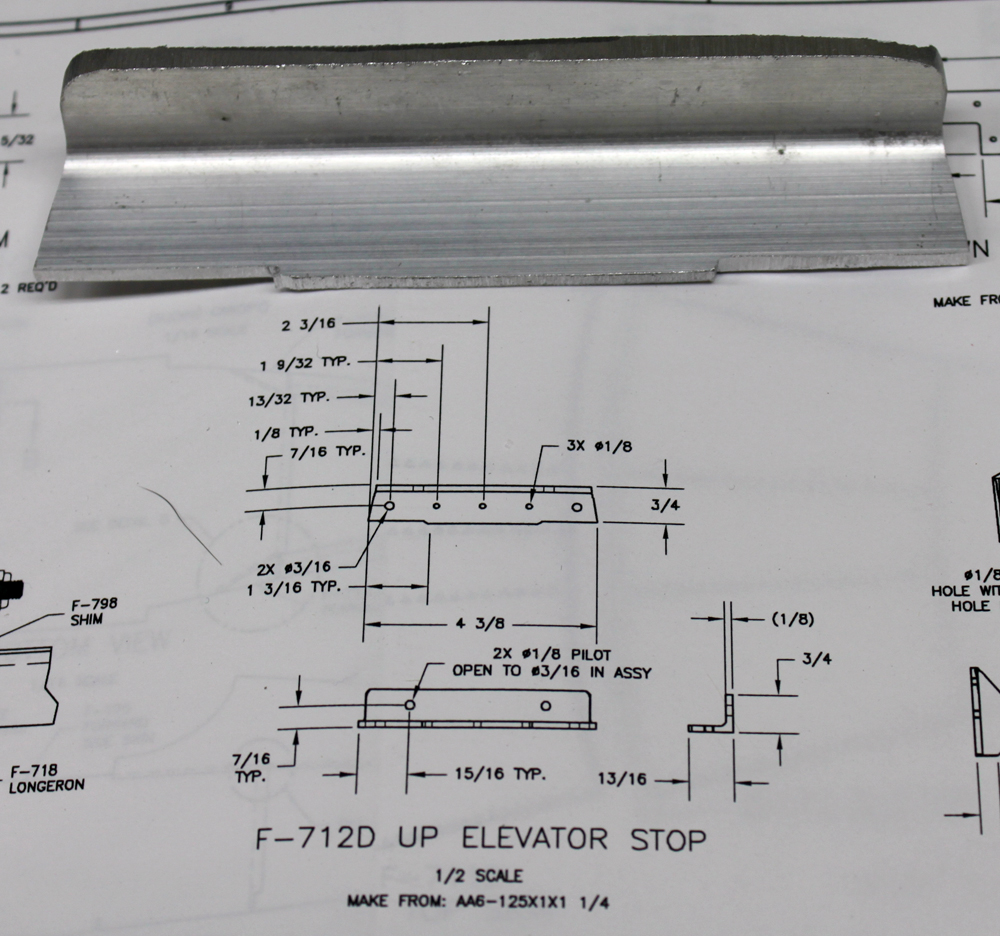
The F-712D up elevator stop is the first part that gets attached to the vertical stabilizer. Here is the rough cut part…it still needs a lot of touching up before it will be ready to be installed.

Finally, one to show the FAA as proof that I’m the builder.

Interesting Stuff


