Posts Tagged priming
Canopy Frame Riveted (5/16/15)
Posted by Ethan Jacoby in Canopy, Construction, Finishing, Forward Fuselage, Fuselage on May 16, 2015
5.0 Hours –
This is another cumulative post about work I’ve done over the last month. Since I’m just getting a little work done now and then, it’s easier to just post progress when “milestones” are reached. The current “milestone” is completion of the canopy frame.
Over the last few weeks, I’ve prepped all the canopy frame parts for riveting. As usual, this included deburring, dimpling, countersinking, scuffing, cleaning, and priming. For the most part, all of this was relatively straight forward, but some areas were more challenging than others. Parts of the forward canopy frame had to be countersunk by hand, and many areas were challenging to reach.
Eventually, all the parts were ready to rivet back together. Unfortunately, almost all the rivets had to be set with a rivet gun and bucking bar. First the top skin was riveted to the frame, then the reinforcements were riveted to the underside of the frame and skin. Overall, it looks good. Hopefully, nothing moved to far out of position and it will still sit nicely on the fuselage. The next steps will be to place the canopy frame back on the fuselage, do some final adjustments on the canopy, and then start drilling the canopy to the frame.

Except for the top of the aft section, the canopy frame is completely riveted and ready to go back on the fuselage.
Forward Canopy Latch Day 3 (4/26/13)
Posted by Ethan Jacoby in Canopy, Construction, Finishing, Forward Fuselage, Fuselage on April 26, 2013
1.5 Hours –
Another short work session, but I managed to get the forward canopy latch finished (except for riveting).
All that was left was to drill the latch to the fuselage. The hardest part of this was trying to figure out a good way to clamp it into position. I kept testing the latch as I drilled to make sure it was still aligned with the slots and allowed to actuate fully.
After drilling, I removed and disassembled the latch in order to complete the remaining finishing work. The angles had to be countersunk, then I cleaned and primed the parts. I also painted the areas of the angle that will be visible after it is riveted to the fuselage. Finally, I deburred and dimpled the holes in the fuselage. I also sprayed some primer on the latch area on the outside of the fuselage. I figure this area could use a little extra protection, and the primer can be easily removed before painting.

Once the latch parts were finished, I gave them a coat of primer. I also painted the faces of the angles that will be visible once installed.

I sprayed a little primer on the fuselage around the latch area. I figure this area may need extra protection in the short-term.
The last thing I did was to work on the fuel line running from the fuel selector to the electric pump. I started working on this a few days ago, but couldn’t get one of the bends to work, and quickly ruined all of my tubing. I found an angled fitting for the fuel pump and ordered that. Once the fitting was installed on the pump, I realized some of the bad lines from the other day might be salvageable, so I picked the best one and cut off the bend on the fuel pump end. Surprisingly, the length of the line was now perfect, and everything lined up, so I put on a new flare and fit the line with the fittings only loosely tightened. That was much easier with the new fitting…wish I would have known about that in the first place!

The angled fuel pump fitting can be seen on the bottom of the fuel pump. This made fabrication of the fuel line much much much easier.

I was able to salvage one of my bad fuel lines to make this good one. The bends in the middle made the length correct. All that is left is to tighten the fittings and wrap the line with some foam.
Vents and Canopy Release (4/16/13)
Posted by Ethan Jacoby in Canopy, Construction, Finishing, Forward Fuselage, Fuselage on April 16, 2013
3.5 Hours –
I received a couple orders from Van’s, so it was time to back track a little. The replacement parts for my left fresh air vent were included in one of the shipments, so I started working on that first. In order to avoid the gap that I had on my first left vent attempt, I mimicked my procedure for the right vent. First, the vent and SCAT coupler were clamped together and two holes were drilled. Then, the aluminum angle was clamped in position and match-drilled to the vent/coupler. Those three parts were then bolted together, and the lower inboard corner was rounded off until the vent fit into the panel. Finally, the whole thing was drilled to the fuselage, and the angle was deburred, dimpled, primed, and riveted. Unfortunately, I had the whole thing disassembled and stored before I thought about taking any pictures. You’ll just have to trust me that this one came out much better with no gap between the vent and the coupler. Time to move on!
Another part that arrived in my order was a new C-620 bearing block. This block holds the canopy release mechanism to the sub-panel, and I screwed up the first one by mounting it too low. Cutting and drilling the new one was a non-event, and I ended up raising it about 1/4 inch from the previous position. Once the new block was done, I was able to assemble the rest of the release mechanism. The instructions are pretty vague, so it took me some time to figure out how to “clock” the lower bellcrank arm and how to install the assembled parts in the fuselage (there was a lot of repositioning of the arms/pins that had to be done…this won’t be easy once the top skin is on and I have to install the mechanism while laying on my back). I had to spend some time studying how the parts moved, but, eventually, I figured it out and was able to connect everything up. There’s still some interference with various parts when the release is actuated, but I think I know how to fix this. However, I’ve already spent a lot of time on this assembly, and my patience was waning, so I decided to move on to something more fun and come back to the release mechanism during my next work session.

The almost complete canopy release mechanism. I’ve spent more time on this than it is worth!

Top view of the release mechanism. All that is missing is the handle that goes through the instrument panel and connects to the bellcrank.
The last thing I did was to assemble my wrench for the main gear axle nuts. Yes, even tools are available from Van’s in kit form! For the wrench, you simply mate the two halves, final-drill, and rivet…I also did some edge finishing and painted it. This is a light-weight solution for the big nuts that hold the wheels onto the main gear legs. Alternatively, you could use a deep socket or an adjustable wrench, but those would be so heavy that you wouldn’t want to carry them in the plane. The Van’s wrench weighs in at only a couple of ounces, so it will be kept in the emergency tool/parts kit that will stay with the finished plane.

Even tools come from Van’s in kit form. This is a wrench for the wheel axle nuts. Just like with the airplane kits, cleco, drill, rivet…easy.
Front Deck Day 8, Canopy Install Started (4/7/13)
Posted by Ethan Jacoby in Canopy, Construction, Finishing, Forward Fuselage, Fuselage on April 7, 2013
5.1 Hours –
I spent a lot of time working on small parts today.
First, I finished all of the angles that attach the instrument panel to the canopy decks. Some of them had to be drilled for platenuts, and all of them had to be primed. Once the primer dried, I installed them in the fuselage.

More priming. These are the various pieces of angle for the instrument panel, as well as the right vent bracket (the left is getting remade).

Two of the instrument panel angles and the right vent bracket installed on the fuselage.
Next, I started working on the canopy hinge spacers. The canopy attaches to the front deck at two spots. Each location uses two plastic and one aluminum spacer to guide the ears of the forward canopy frame into position. To make the spacers, one of the plastic ones was fabricated using the dimensions on the plans, then the other two were match-drilled to the first. At this point, they could all be fit to the front deck and final-drilled to the deck ribs. In order to make sure the front deck was properly aligned, I re-attached the forward top skin and then lifted each side to drill through the spacers and ribs.

The C-617 spacers are made from plastic and match-drilled to the front deck ribs.

Another view of the C-617 spacers being drilled to the front deck.

The C-617, C-618 and 619 spacers all had to be fabricated from stock material.

All of the canopy hinge spacers installed and ready for match drilling to the F-644 rib on the center sub-panel.

The canopy hinge spacers are finished.
Prior to drilling the 1/4 inch hole through the F-644 rib, I made the modified canopy hinge pins. These are eye bolts that have the threads ground off…making them a pin instead of a bolt. These pins hold the canopy to the frame and get moved in and out of the spacer blocks when the canopy jettison mechanism is activated.

The pins that hold the canopy on are just modified eye-bolts.
Front Deck Day 5 (4/1/13)
Posted by Ethan Jacoby in Construction, Forward Fuselage, Fuselage on April 1, 2013
1.8 Hours –
The end of my front deck work is in sight, but I didn’t get there today.
Today, I managed to get the right sub-panel assembled. This involved riveting the seal support angle to the right sub-panel and then riveting the right rib to the sub-panel with only two rivets (the other rivets are left open for now since they are used to attach the center sub-panel.

The right section of the front deck after riveting the seal support angle, sub-panel and rib together.
Next, I further assembled the center sub-panel section by riveting on the F-697 and the center channel. I back-riveted these using my c-frame. This has become my preferred riveting method when the parts are still on the workbench and I can’t squeeze the rivets.

The center section of the front deck. The F-697 and center channel were back-riveted with my c-frame.
Finally, I removed the left sub-panel assembly from the fuselage and completed all of the deburring and prep work. This wrapped up with a coat of primer. Tomorrow, I’ll rivet it together.

The parts for the left side of the front deck are now primed and ready to be assembled.
All that is left is to make two more angles that attach the panel to the canopy decks, and two angles for attaching the fresh air vents to the panel and fuselage. I’ll probably go ahead and fit the front top skin before moving on to other areas as well.
Front Deck Day 4 (3/30/13)
Posted by Ethan Jacoby in Construction, Forward Fuselage, Fuselage on March 30, 2013
3.7 Hours –
After finishing the inventory of my finish kit, I’m finally back to construction. With today’s work, I passed the 1000 hour milestone as well. I figure I’m 2/3 done and still have another 500 hours of work before I’m done.
I was fortunate that my finish kit arrived when it did because one of the front deck parts for the tip-up canopy is included with the finish kit, not the fuselage kit. The F-697 is just an aluminum channel, so I’m not sure why it doesn’t come in the fuselage kit. The part had to be cut to the correct length, and tapered on one end, before being match-drilled to the center section of the front deck. Also, while reviewing the plans, I realized that riveting the F-697 now would have made installation of some of the parts for the canopy release mechanism much more difficult. So, I went ahead and made the bearing block for the release mechanism and drilled that to the F-697. I’m still not sure if I’m going to install the release mechanism, but at least I’ll have the option.
Next, I drilled the center channel to the center section and F-697. This part also had to be slightly modified for the release mechanism.
Finally, I prepped and primed all of the finished parts I had.
There aren’t many pictures today. Something is wrong with my camera (I think it is just my memory card). Several of my pictures didn’t save correctly, and I couldn’t download them to the computer. Oh well!

The F-697 is modified, then drilled to the center section of the front deck.

More priming. This is the F-697, one of the front deck ribs, and the front deck center channel.
Cabin Frame Day 4 (2/24/13)
Posted by Ethan Jacoby in Center Fuselage, Construction, Fuselage on February 24, 2013
4.0 Hours –
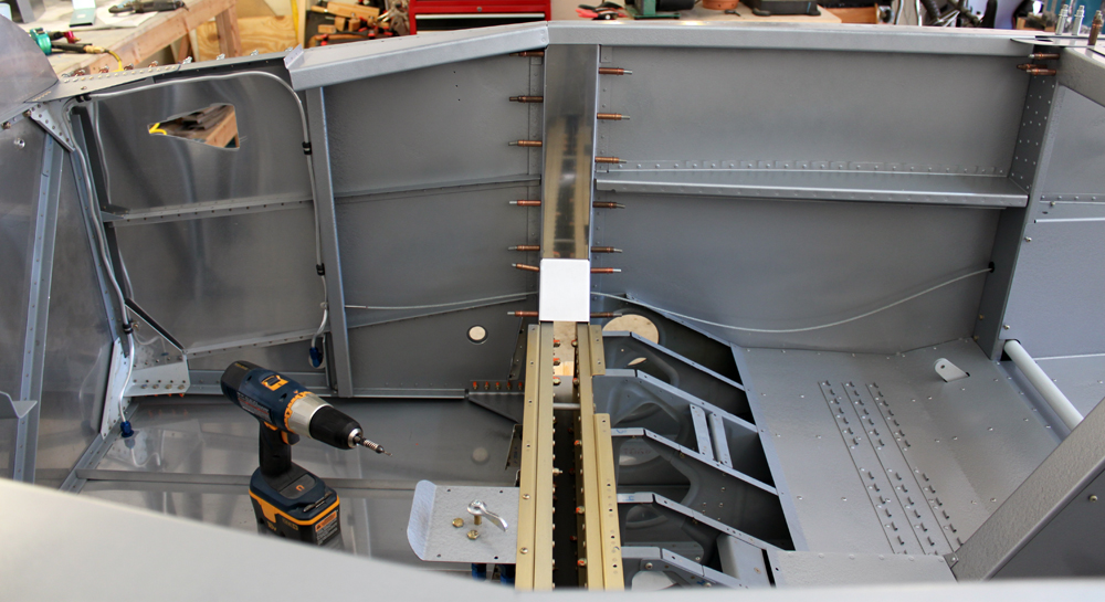
Another four hours of work on the cabin frame, but at least I have a completed frame assembly to show for it!
I started off by deburring all the parts that had not been finished yet. This was followed by scuffing, cleaning and priming. For now, I’m only priming the parts that will be on the inside of the assembly. I’ll prime and paint the outside later on after the frame has been fit to the fuselage.

The cabin frame parts are ready for primer. I’ll only prime the inside for now.
After the primer dried, I started assembly by riveting the F-631E plates to the frame sections. These plates tie the frame sections together to form the front and back halves of the frame. On the aft half of the frame, I also riveted the F-732D angle.

The F-631E plates and the F-732D bracket get riveted to the frame halves first.
Next, the F-631B and F-631B-L straps were riveted to the forward half of the frame. Solid rivets are used to rivet the straps on the forward half, and all the rivets could be squeezed, so it was a pretty easy task.

The straps are riveted to the forward half of the frame first using solid rivets. The aft half will be attached with blind rivets.

The forward half of the frame is done,
Once the straps were riveted to the forward half, the aft half of the frame was placed into position and riveted. Since there is no access to the inside of the frame structure once the aft half is in position, the aft half must be attached with CS4-4 blind rivets. While these rivets are relatively easy to pull, there are so many of them that it gave my forearms a pretty good workout, but it was worth it to see the finished assembly!

The aft half of the frame is riveted using CS4-4 blind rivets.

The completed frame.

An end view of the frame channel showing the rivets and straps.

The shanks from all the blind rivets I installed today. My forearms were a little tired after all this!
Finally, I started working on the brackets that connect the cabin frame to the fuselage. The brackets are made by combining two of the angles fabricated earlier (F-631C and D) into an offset “U” shape. To get the correct width for the brackets, the angles are clamped to the ends of the cabin frame channel and then two keeper rivet holes are drilled. The keeper rivets, which I haven’t installed yet, will allow the brackets to keep their shape, without any clamps, during the rest of the fitting process.

The angles made earlier are clamped to the ends of the cabin frame in order to make mounting brackets for the frame.

The brackets for both sides of the frame. These will get a couple of keeper rivets so they can stay together without the clamps.

My progress for the day…a completed cabin frame and a good start on two brackets.
F-704K Upright Cap Strips (2/17/13)
Posted by Ethan Jacoby in Center Fuselage, Construction, Fuselage on February 17, 2013
1.8 Hours –
Although I had the time, today wasn’t a big airplane day. I was lacking motivation to work on the airplane, or do just about anything else. All in all, a pretty lazy day.
The section of hinge on the bottom of the seat backs still needed to be riveted. Now that I knew the seats fit well, I could go ahead and rivet the hinge. All of these rivets could be squeezed, so it didn’t take much time to complete.
I’m at the point now where I don’t necessarily go step by step in the instructions. For one, the instructions have become incredibly vague. In addition, I like to tailor my work to what I think I will have time to finish. Now, I simply look at what parts I have remaining, and then decide what I want to work on for the day.
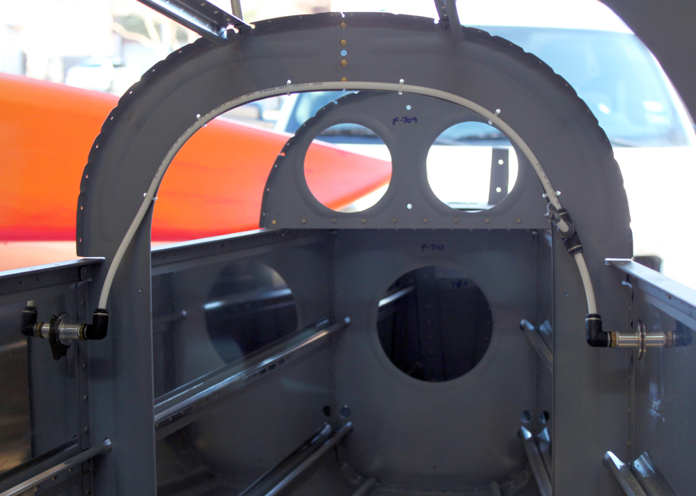
Today, I decided to work on the F-704K upright cap strips. These pieces cover up the gap between the vertical sections of the F-704 bulkhead. The left F-704K fit perfectly, but the right needed a little trimming because part of the canopy deck flange interfered. Once the parts were clecoed on, I simply final-drilled them and then took them off for deburring, priming, and paint. The F-782 cover plates also needed to be painted, so I quickly completed the deburring that needed to be done on those so they could be painted at the same time as the F-704Ks.
The right F-704K upright cap strip fit to the F-704 bulkhead.

More priming and painting. Here the F-704K upright cap strips and the F-782A cover plates have been primed.
Interior Painted (1/20/13)
Posted by Ethan Jacoby in Center Fuselage, Construction, Forward Fuselage, Fuselage on January 20, 2013
0.8 Hours –
It was a pretty short day in the garage today. I picked up the interior pain in the morning, so, of course, I was anxious to use it. I had already scuffed and cleaned the areas that I wanted to paint, but I still went over them a second time with some acetone to make sure they were as clean as I could get them. I then masked off the outside of the fuselage to protect from over-spray. Once masked, pulled out the primer and sprayed away. Once the primer coat was on, I added the paint…Rustoleum hammered silver. I tried to paint only the areas that will be visible in the finished airplane. If an area is to be covered with a panel of some sort, I didn’t paint it. I also didn’t paint the forward most section of the fuselage between the forward-most vertical bulkhead and the firewall. I figured this area would be only slightly visible, and only if you were looking at the rudder pedals. I’ll give the paint a day to cure, and then I’ll try to be very cautious around the paint for at least another week as it continues to fully cure. From this point on, anything that gets added to the fuselage will get painted before it gets riveted.

The interior after paint. You can see that some areas are painted and some aren’t. The unpainted areas will get covered up by panels later.
Miscellaneous Tasks Again (1/19/13)
Posted by Ethan Jacoby in Aft Fuselage, Center Fuselage, Construction, Fuselage on January 19, 2013
3.0 Hours –
I worked on a few more miscellaneous things today. First, I finished prepping the lower baggage bulkhead, including primer and paint.
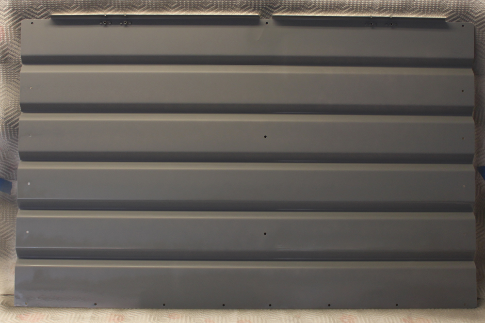
The lower baggage bulkhead primed and ready for paint.
Next, I installed some tubing that connects the two static ports together. There’s no real need to install this now, other than to close the system, preventing debris from getting into the ports. I placed a tee connection on the left side. Eventually, a tube will run from the tee to wherever my ADAHRS (air data and compass module) are located. However, for now, I just attached a short length of tubing and closed off the end with some duct tape to make sure nothing could get in.
I installed the tubing that connects the static ports together. I did this now mainly to keep dirt, and other stuff, out of the system.
After taking a short break, I returned to the plane and prepped and painted the aft baggage covers. At this point, I think I want to paint anything going into the plane before it gets riveted. Along that line, I also decided to start getting the inside of the fuselage ready for paint. My plan is to paint everything from the F-706 bulkhead forward to where the sub-panel will be. That should cover everything that is visible. The floor forward of the F-704 won’t get painted though, as that will be covered with carpet. Similarly, I won’t paint anything that will later be covered by a floor board or access panel. Less paint equals less weight!

Interesting Stuff


