Posts Tagged deburring
Canopy Frame Riveted (5/16/15)
Posted by Ethan Jacoby in Canopy, Construction, Finishing, Forward Fuselage, Fuselage on May 16, 2015
5.0 Hours –
This is another cumulative post about work I’ve done over the last month. Since I’m just getting a little work done now and then, it’s easier to just post progress when “milestones” are reached. The current “milestone” is completion of the canopy frame.
Over the last few weeks, I’ve prepped all the canopy frame parts for riveting. As usual, this included deburring, dimpling, countersinking, scuffing, cleaning, and priming. For the most part, all of this was relatively straight forward, but some areas were more challenging than others. Parts of the forward canopy frame had to be countersunk by hand, and many areas were challenging to reach.
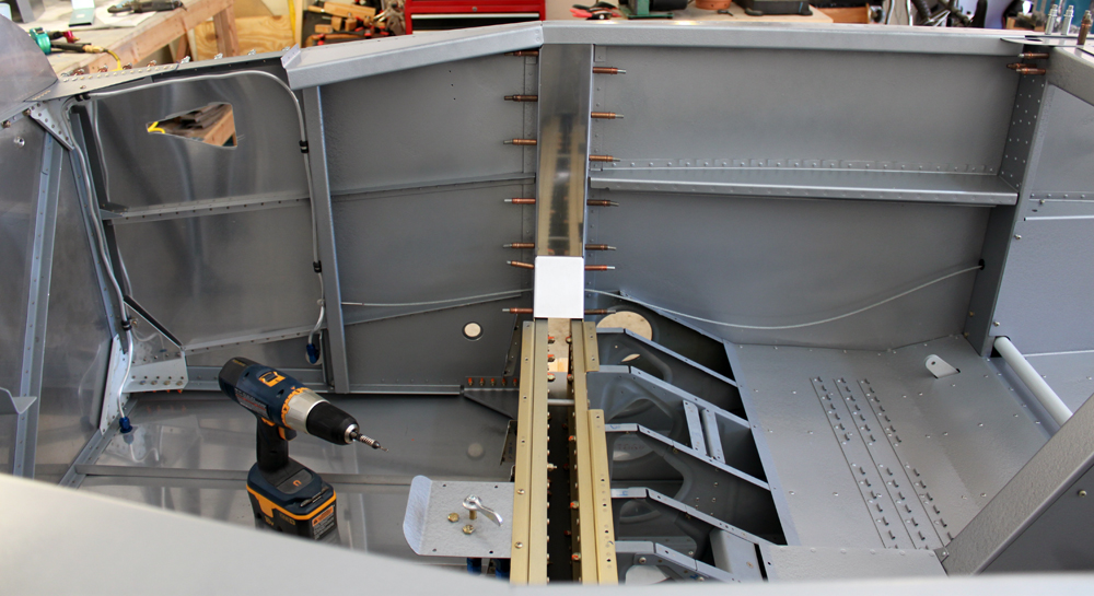
Eventually, all the parts were ready to rivet back together. Unfortunately, almost all the rivets had to be set with a rivet gun and bucking bar. First the top skin was riveted to the frame, then the reinforcements were riveted to the underside of the frame and skin. Overall, it looks good. Hopefully, nothing moved to far out of position and it will still sit nicely on the fuselage. The next steps will be to place the canopy frame back on the fuselage, do some final adjustments on the canopy, and then start drilling the canopy to the frame.

Except for the top of the aft section, the canopy frame is completely riveted and ready to go back on the fuselage.
Forward Canopy Latch Day 3 (4/26/13)
Posted by Ethan Jacoby in Canopy, Construction, Finishing, Forward Fuselage, Fuselage on April 26, 2013
1.5 Hours –
Another short work session, but I managed to get the forward canopy latch finished (except for riveting).
All that was left was to drill the latch to the fuselage. The hardest part of this was trying to figure out a good way to clamp it into position. I kept testing the latch as I drilled to make sure it was still aligned with the slots and allowed to actuate fully.
After drilling, I removed and disassembled the latch in order to complete the remaining finishing work. The angles had to be countersunk, then I cleaned and primed the parts. I also painted the areas of the angle that will be visible after it is riveted to the fuselage. Finally, I deburred and dimpled the holes in the fuselage. I also sprayed some primer on the latch area on the outside of the fuselage. I figure this area could use a little extra protection, and the primer can be easily removed before painting.

Once the latch parts were finished, I gave them a coat of primer. I also painted the faces of the angles that will be visible once installed.

I sprayed a little primer on the fuselage around the latch area. I figure this area may need extra protection in the short-term.
The last thing I did was to work on the fuel line running from the fuel selector to the electric pump. I started working on this a few days ago, but couldn’t get one of the bends to work, and quickly ruined all of my tubing. I found an angled fitting for the fuel pump and ordered that. Once the fitting was installed on the pump, I realized some of the bad lines from the other day might be salvageable, so I picked the best one and cut off the bend on the fuel pump end. Surprisingly, the length of the line was now perfect, and everything lined up, so I put on a new flare and fit the line with the fittings only loosely tightened. That was much easier with the new fitting…wish I would have known about that in the first place!

The angled fuel pump fitting can be seen on the bottom of the fuel pump. This made fabrication of the fuel line much much much easier.

I was able to salvage one of my bad fuel lines to make this good one. The bends in the middle made the length correct. All that is left is to tighten the fittings and wrap the line with some foam.
Forward Canopy Latch Day 2 (4/24/13)
Posted by Ethan Jacoby in Canopy, Construction, Finishing on April 24, 2013
1.6 Hours –
With a little free-time this evening, I decided to continue working on the forward canopy latch. The first thing I had to do was to finish deburring the C-609. Normally, deburring is a pretty easy task, but the C-609 and C-607 both have a lot of complex curves, angles, etc, that make deburring a bit of a pain. However, eventually, the job was done.
With the handle parts finished, I temporarily bolted them to the lower C-712 angle. I wanted to test the mechanism to make sure there was enough clearance for the C-607 and C-609 to move through their entire range of motion, and I wanted to make sure they were close enough that they could latch together in the closed/locked position. After all, a latch that doesn’t latch is worthless!

Here’s the forward latch, without the upper angle, showing the closed/locked position.

The unlocked position.

And, the open position.
Since everything went together nicely, I went ahead and made the upper C-712 angle. To match-drill the bolt holes, I clamped the upper and lower angles together, and then clamped them to a heavy piece of aluminum angle. This ensured that the parts were lined up correctly, and the outboard faces were flush with each other. Once everything was clamped, I simply drilled the bolt holes through to the upper angle.

To make sure the angle faces were flush, and to ensure nothing moved while match-drilling the bolt holes, I used an assortment of clamps. Yes, this was probably overkill…but, nothing moved!

A top view of the assembled latch. The large hole is partially covered by a spacer which won’t be there in the final product.
Next, I cut the slots in the fuselage side skin. These slots are where the handles protrude outside the plane, and they are also the part of the latch that I was least looking forward to completing. It isn’t hard to make the slots, but cutting into a flawless skin isn’t an easy task to work up to sometimes. However, everything went well as I made the initial cuts with a Dremel and cutoff disk. Then, I did a lot of filing and sanding to clean up the slots and make sure they were wide enough for the handles.

I finally worked up the courage to slot the fuselage side skin. It turned out pretty good.

The slots on the inside.

I’m holding the latch in position just to test that the slots are long enough for the mechanism to clear.
All that is left now is to drill the angles to the side skin, complete the usual finishing tasks, and rivet the whole thing to the fuselage.
Forward Canopy Latch Started (4/23/13)
Posted by Ethan Jacoby in Canopy, Construction, Finishing on April 23, 2013
1.0 Hours –
Today, I started working on the forward canopy latch mechanism. This is a simple latch mechanism that can be actuated from inside the or outside the airplane. The handle is connected to the aft portion of the latch mechanism, located on the F-705 bulkhead, using a pushrod.
The first thing I did was to use the provided template to find the location of the handle on the forward fuselage side skin. Once the position was located, I taped the template in place and used it to drill the holes that will be used to rivet the handle in place. For now, I just drilled the holes, but I’ll have to make two slots by cutting material from between some of the holes. I didn’t feel like slicing up the fuselage skin today though!

I positioned the template for drilling the holes for the forward latch, and drilled the holes. I still need to make the slots.
Next, I cut the C-712 angles to length. These are the angles that will hold the handle in position on the fuselage side skin. Once the angles were cut, I focused on the lower angle, drilling it for two bolts and also cutting a relief for the end of the pushrod.
Finally, I started deburring the handle parts. I was only able to finish the C-607, the larger of the two parts. There are a lot of angles, curves, notches, etc, on these parts, so it takes some time to deburr them properly.

My progress for the night. I made the bottom C-712 angle, and cut the top C-712 angle to length. I also deburred the C-607 latch handle.
Front Deck Day 3 (3/24/13)
Posted by Ethan Jacoby in Construction, Forward Fuselage, Fuselage on March 24, 2013
1.3 Hours –
I didn’t have a lot of time to work on the plane today. However, I managed to finish the initial assembly of the front deck. I finished final-drilling the entire front deck, and then I match-drilled the F-721C angles to the canopy decks. These angles tie the instrument panel to the canopy decks, so I wanted to do the drilling now while everything was in place. Finally, I started working on deburring some of the parts, but I didn’t get very far before I had to leave for the day.

The F-721C angles are drilled to the canopy decks.

Another view of the connection of the panel to the canopy decks.
Cabin Frame Day 4 (2/24/13)
Posted by Ethan Jacoby in Center Fuselage, Construction, Fuselage on February 24, 2013
4.0 Hours –
Another four hours of work on the cabin frame, but at least I have a completed frame assembly to show for it!
I started off by deburring all the parts that had not been finished yet. This was followed by scuffing, cleaning and priming. For now, I’m only priming the parts that will be on the inside of the assembly. I’ll prime and paint the outside later on after the frame has been fit to the fuselage.

The cabin frame parts are ready for primer. I’ll only prime the inside for now.
After the primer dried, I started assembly by riveting the F-631E plates to the frame sections. These plates tie the frame sections together to form the front and back halves of the frame. On the aft half of the frame, I also riveted the F-732D angle.

The F-631E plates and the F-732D bracket get riveted to the frame halves first.
Next, the F-631B and F-631B-L straps were riveted to the forward half of the frame. Solid rivets are used to rivet the straps on the forward half, and all the rivets could be squeezed, so it was a pretty easy task.

The straps are riveted to the forward half of the frame first using solid rivets. The aft half will be attached with blind rivets.

The forward half of the frame is done,
Once the straps were riveted to the forward half, the aft half of the frame was placed into position and riveted. Since there is no access to the inside of the frame structure once the aft half is in position, the aft half must be attached with CS4-4 blind rivets. While these rivets are relatively easy to pull, there are so many of them that it gave my forearms a pretty good workout, but it was worth it to see the finished assembly!

The aft half of the frame is riveted using CS4-4 blind rivets.

The completed frame.

An end view of the frame channel showing the rivets and straps.

The shanks from all the blind rivets I installed today. My forearms were a little tired after all this!
Finally, I started working on the brackets that connect the cabin frame to the fuselage. The brackets are made by combining two of the angles fabricated earlier (F-631C and D) into an offset “U” shape. To get the correct width for the brackets, the angles are clamped to the ends of the cabin frame channel and then two keeper rivet holes are drilled. The keeper rivets, which I haven’t installed yet, will allow the brackets to keep their shape, without any clamps, during the rest of the fitting process.

The angles made earlier are clamped to the ends of the cabin frame in order to make mounting brackets for the frame.

The brackets for both sides of the frame. These will get a couple of keeper rivets so they can stay together without the clamps.

My progress for the day…a completed cabin frame and a good start on two brackets.
Cabin Frame Day 3 (2/23/13)
Posted by Ethan Jacoby in Center Fuselage, Construction, Fuselage on February 23, 2013
4.0 Hours –
I bought a new center punch at Home Depot this morning, so I’m back in business on the cabin frame. The new center punch is the same design as my old one, but this one seems heavier and a little more robust. Maybe it is the deluxe model (I did pay $10 for it)!

With a new center punch, I’m back in business.
The first thing I did was to drill the locations of the rivet holes on the forward halves of the frame. As with the aft half, I decided to drill them to #40 first, then match-drill them to the straps, then enlarge all the holes to #30. Drilling the forward half to the aft half and straps was pretty simple since my frame turned out to be the perfect width if I just made sure it was all pressed together.

The forward half of the frame is drilled to the aft half and straps.
Once the forward half was drilled to the assembly, I match-drilled the second F-631E plate. This plate will eventually go on the inside of the structure, but it is easier to match-drill it if it is on the outside. I also positioned and drilled the F-732D angle to the top of the aft side of the frame.

The second F-631E is match-drilled to the forward half of the frame. This will go on the inside of the frame, but match-drilling on the outside achieves the same fit.
Next, I enlarged all the holes to #30. This took no time at all as the #40 holes were already in place and acted as pilot holes. Moving clecos was the only thing that slowed me down.

After everything was drilled, I enlarged all the holes to #30.
Countersinking all the holes was the next step, and it was what took up most of my time today. Normally, I simply don’t like countersinking, but countersinking around a curved structure is a real pain. Due to the curves, the countersink cage won’t sit flush on the material, leaving most of the countersinks too shallow. Because of this, I had to check the depth of every countersink with a rivet and then enlarge the countersinks, as needed, by hand. Eventually, I finished countersinking the entire frame structure, which is probably around 300 holes. Fun!

I managed to get all the countersinks completed around the outside and inside curves of the frame. I hate countersinking and the curve of the frame didn’t make it any easier!
Once all the countersinking was done, I started taking the frame apart for deburring and various other finish tasks. I should be able to finish the prep work and start final assembly tomorrow.
F-704K Upright Cap Strips (2/17/13)
Posted by Ethan Jacoby in Center Fuselage, Construction, Fuselage on February 17, 2013
1.8 Hours –
Although I had the time, today wasn’t a big airplane day. I was lacking motivation to work on the airplane, or do just about anything else. All in all, a pretty lazy day.
The section of hinge on the bottom of the seat backs still needed to be riveted. Now that I knew the seats fit well, I could go ahead and rivet the hinge. All of these rivets could be squeezed, so it didn’t take much time to complete.
I’m at the point now where I don’t necessarily go step by step in the instructions. For one, the instructions have become incredibly vague. In addition, I like to tailor my work to what I think I will have time to finish. Now, I simply look at what parts I have remaining, and then decide what I want to work on for the day.
Today, I decided to work on the F-704K upright cap strips. These pieces cover up the gap between the vertical sections of the F-704 bulkhead. The left F-704K fit perfectly, but the right needed a little trimming because part of the canopy deck flange interfered. Once the parts were clecoed on, I simply final-drilled them and then took them off for deburring, priming, and paint. The F-782 cover plates also needed to be painted, so I quickly completed the deburring that needed to be done on those so they could be painted at the same time as the F-704Ks.
The right F-704K upright cap strip fit to the F-704 bulkhead.

More priming and painting. Here the F-704K upright cap strips and the F-782A cover plates have been primed.
Flaps Mechanism Continued (1/26/13)
Posted by Ethan Jacoby in Center Fuselage, Construction, Fuselage on January 26, 2013
5.6 Hours –
Today, I’m back to work on the flaps…or, more correctly, the flap actuator mechanism. The entire mechanism is basically a motor that is attached to a couple braces in the fuselage. The motor is connected to a weldment that is connected to the actual flaps on the wings. Much like the rest of the plane, its simple and it works.
The first thing I wanted to do was to install the flap weldment. The side bearing blocks had been fitted to the fuselage much early, so all I had to do was bolt the blocks in along with the weldment. The F-680 center bearing block needed to be drilled to the floors, but I ran into a problem here. Although I drilled the block per plans, the forward hole was too far forward. If I would have drilled it where it was, I would have missed the flange of the F-705 bulkhead. I’m going to order a new block ($8.70 from Van’s) and try again. This time, however, I’m going to drill the forward hole slightly more aft than the plans call for.

I drilled the F-680 bearing block per plans, but it doesn’t fit right. The holes are hard to see, but the forward hole is too far forward. I’ll get a new one and drill the hole a bit further aft than the plans call for.
Even though the bearing block didn’t fit right, I was able to use it to mark and trim the baggage tunnel cover. Once this was done, the tunnel cover was finished, to I prepared it, along with the aft seat floors for primer and paint.

The baggage tunnel cover and aft seat floors are ready to be primed and painted.
Next, I started working on the various braces and brackets that hold the flap motor in place. Several parts needed to be fabricated from stock, while other parts were already finished and ready for assembly. Since there was a lot of fabrication work, it took quite a bit of time. Rather than explaining everything I did, I’ll just let the pictures tell the story.

The first of the flap parts to fabricate was the F-766C bracket. Only one hole is drilled now, the rest are drilled in assembly with the F-766A actuator channel.

The F-766C drilled to the F-766A channel.

The F-758 brackets are riveted to the bottom of the F-766A channel.

The F-766C bracket is riveted to the F-766A channel using flush rivets. I also riveted all the platenuts to the sides of the channel using NAS1097 “oops” rivets.

The F-766B bracket also had to be fabricated from a piece of angle stock. Van’s includes two pieces of stock. I’m not sure if other planes require two, or if they just assume you will mess up the first!

The F-785B bracket must be fabricated as well. It links the F-785A back rest brace to the baggage floor.

The F-767 plate must be fabricated from stock material. It only has to be cut to size and bent. It will get drilled in assembly later.

All of the flap mechanism parts I worked on today.

A closer view of the brackets and spacers for the flap mechanism.
Baggage Side Covers and Floors (1/21/13)
Posted by Ethan Jacoby in Center Fuselage, Construction, Fuselage on January 21, 2013
2.8 Hours –
My next task was to install the forward baggage covers. Installation of these uses a number of different fasteners. The aft flange is riveted to the F-706 bulkhead with flush solid rivets, the upper edge is riveted to the horizontal baggage rib with blind rivets, and the forward edge is riveted to the vertical baggage rib using some NAS1097 “oops” rivets along with platenuts. Many builders install the rudder cables before riveting the aft baggage covers, but, in a test, I used a piece of safety wire to pull the rudder cable through bulkheads. This was easy to do, so I decided to leave the safety wire in place and install the cables at a later time. At least this will keep them out of my way.

The aft baggage covers are installed.
Next, I trimmed the upper flange of the forward baggage covers, and then deburred the parts. I also took a few minutes to install my tie-down ring “storage system.” Once the forward covers prep was finished. I prepared both the forward covers and the baggage floors for paint. The inside of the parts got primed only, while the outside was primed and painted. I really like the hammered silver paint. The inside of the fuselage looks good, and it looks better with each painted part I add.

A view of the baggage area. You can see the difference between the painted and unpainted areas. The forward baggage cover is clecoed for now, but it still needs some platenuts and paint.

I installed my home-made platenuts on the inside of the forward baggage covers. These should be a nice place to store the tie down rings.

A view of the tie down ring “storage system” from the outside.

More painting. These are the baggage floors and forward baggage covers.

A closer view of the painted forward baggage cover. I really like the hammered look.

Interesting Stuff


