Posts Tagged pitot tube
Wings Complete!!! (12/4/11)
Posted by Ethan Jacoby in Ailerons, Construction, Flaps, Main Structure, Wings on December 4, 2011
2.3 Hours –
The wings are now completely finished!!! That’s not even one of my usual “finished except for…” lead-ins. They are now going to sit as they are until it’s time to mate them to the fuselage. Speaking of the fuse, I received a shipment notice/tracking number from Van’s, and the fuselage is scheduled to be delivered by ABF on 12/7/11. Great timing!
The work I did today to finish the wings was pretty easy. The first thing I did was to reinstall the left aileron on the wing. To make this a little easier, I decided to install the push-rod on the aileron while the aileron was sitting on a work bench. Once the push-rod was attached, I could insert it into the aft end of the wing before positioning the aileron on its brackets. Once the aileron was positioned, it took a little time to get all the washer/spacers into the correct positions, and I also had to remake one spacer (the original was too short and I didn’t catch it before), but I eventually got everything connected.
I forgot to mention a new tool previously, but I did spend $30 to get a set of washer wrenches from Avery Tools. They seemed a little expensive for what they are, but they really do make washer insertion much easier. In my opinion, they pretty much paid for themselves during aileron installation.

The Avery washer wrench set has a total of four wrenches like this one. Each wrench holds two different sizes of washers.
Next, I riveted the pitot mast to the left wing. The mast attaches with only 5 rivets, but I managed to screw up one of those. I had been doing great with my riveting, with almost no re-dos on the bottom skins, so I guess I was due. In addition, as I was working on the mast, I had my first broken cleco. The cleco wouldn’t stay in the wing. When I checked it, I found that one of the small “dogs” had broken off. Unfortunately, this is an unfixable issue. However, this little cleco had seen a lot of use…you can still see some of the tank sealant on it from when it was used on the fuel tanks.
Once the mast was riveted, I routed the pitot/AOA tubing through the wing. For now, I have it running under the bellcrank. It looks like it should be fine, but I may decide to anchor it to the spar sometime down the road.

For now, the pitot/AOA tubing is routed under the bellcrank. I may clamp it to the spar sometime in the future.
With the tubing in the wing, I decided to go ahead and install the pitot/AOA tube as well. This was just a matter of pushing the two tubes into the fittings, and then using four #6 screws to attach the pitot tube to the mast. I had purchased a cheap pitot tube cover, but it is about an inch too short for the Dynon pitot/AOA. It will function OK for keeping the pitot tube clean in the garage, but I’ll have to buy or make something else once the plane is ready to fly.

My cheapo pitot cover is a bit small. I'll have to buy a different one or maybe make one. Of course, the old rubber chicken is always an option!
Next, I reinstalled the flaps on both wings. With the wings in the cradle, installation of the hinge pins is a bit tricky, so I don’t have them in all the way yet. I really hope they are easier to install once the wings are on the plane!
The last thing I did was to install the access cover plates on the left wing. With the covers in place, there was nothing left to do with the wings but try to find a good place for storing them in the garage while the fuselage is built.
LED Drivers For Nav Lights Installed (10/18/11)
Posted by Ethan Jacoby in Construction, Wings, Wingtips on October 18, 2011
1.3 Hours –
Cooler temperatures, combined with getting a few home improvement projects out-of-the-way, allowed me to finally get back to airplane building tonight! There are a few final touches on the wings that I wanted to work on before riveting the last bottom skins on. Plus, I’ve got some extra motivation to finish the wings now that my fuselage kit will be arriving in just a couple of months.
The first thing I wanted to work on was to install the LED drivers/filters on the outboard wing ribs. Previously, I had made a drill template using Google Sketch-up, and transferred the paper template to a piece of aluminum sheet to provide some rigidity to the guide. After some indecision about where exactly to install the drivers, I settled on the bottom, aft area of the outboard leading edge ribs. With the drill guide in place, I started drilling the four holes that will be used to install the drivers with four #4 screws and lock washers. As it turns out, I can still easily access the driver screws even after the last bottom skin is riveted. I may go back and add some Loctite to these screws, but at least I know I can inspect the screws anytime the wingtips are off.

Google Sketch-up made it easy to make a paper drill template. I transferred this to aluminum to give me a more rigid platform.

I used my drill guide to install the LED driver in the lower, aft corner of the outboard leading edge rib.

A closer view of the installed driver. One power wire will come into the driver, and two wires (power and ground) will go to the nav LEDs in the wingtip.
Next, I wanted to make a small adjustment to my pitot mast installation. When I originally installed the mast, it ended up just slightly askew. This was so slight, that it probably wouldn’t amount to much error, but I wasn’t happy about it. To fix this, I just realigned the bad side of the mast and enlarged some of the holes to #30 in order to account for the shift. During final installation, I can either use 4- rivets or NAS1097 “oops” rivets. Most likely, I’ll go with the 4- rivets since these will be on the bottom of the wing where no one will ever see the different head size.
Since I had to remove the right wingtip prior to installation of the LED driver, I decided this would be a good time to install the nav/strobe assembly and lens in the tip. This only involved 8 screws, so it didn’t take long, but it was nice to see the wingtip complete. My homemade nav/strobes may not have saved me much money over buying some pre-made ones, but I greatly prefer the look of mine!
Skin Prep Finished and Pitot Tube Assembled (2/19/11)
Posted by Ethan Jacoby in Construction, Main Structure, Wings on February 19, 2011
3.4 Hours –
There are a lot of pictures for this post. Some of them may seem a little repetitive on the pitot/AOA portion, but I wasn’t able to find many good descriptions for assembling the Dynon pitot/AOA with the SafeAir1 mast. Hopefully, my description and pictures will help out someone else.
Since deburring doesn’t make any noise that will wake up the neighbors, I started on the project relatively early this morning . OK, it probably wasn’t early by most people’s standards, but I know some people were still asleep in the neighborhood. After about a half hour, I had all the holes on the left bottom outboard skin deburred. Once deburred, I transitioned to dimpling and used my squeezer to dimple all the holes that it could reach. By this time, I figured it was late enough to start making some noise, so I pulled out my c-frame to finish the dimpling process. To wrap up my morning session, I scuffed cleaned and primed the inside surface of the skin.
After lunch, I returned to the garage. Before I could start riveting the left bottom outboard skin, I needed to finish the pitot assembly. This could be done after the skin is riveted, but doing it now lets me see how things are going together inside the wing. Once the skin is riveted, I’ll just have to attach the pitot tube to the mast and connect the air lines.
The first thing that needed to be done was to match drill the mast and pitot. Unfortunately, neither of these have any holes to use as initial guides. The only indicator of hole location is on the pitot tube itself, where there are areas with thicker metal that indicates the proper location for the holes. I used a sharpie to draw lines on the outside of the tube where these thicker areas were. I could then insert the tube part way into the mast and transfer the lines to the mast.

The pitot tube has to be drilled through the sections that have extra metal...marked with lines here.
To drill the holes, I started with the mast. After some careful measurement to determine the proper distance that the holes needed to be from the end of the mast, I center punched the mast and drilled the initial holes to #40. These will have to be enlarged, but not until I know everything is lining up.
With holes drilled in the mast, I reinserted the pitot tube. The lines on the tube were visible through the holes in the mast, so I knew the holes were in the right position. The pitot tube was a little loose inside the mast, so I wrapped a couple layers of aluminum tape around it before drilling. These two, thin layers of tape gave the pitot enough extra thickness for a tight fit in the mast.

The lines on the pitot tube are visible through the holes in the mast. This is a good sign, but I'm still nervous about drilling into a $200 part!
I then drilled the holes in the pitot using the mast holes as a guide. I did this extremely slowly because, if I was off, I could easily drill through the tubing inside the pitot. If this were to happen, the pitot would be ruined ($200 down the drain). After drilling the holes in the pitot, I tapped them for #6 screws.

After drilling the holes into the pitot tube, I tapped them for #6 screws. I also placed two layers of aluminum tape around the pitot to give it a snug fit in the mast.
Next, I enlarged the holes in the mast in order to accommodate #6 screws. I opted for flush screws, so I needed to countersink the mast. Since the mast is curved, a countersink cage would not work, and I decided to countersink by hand using a deburring tool. This method doesn’t create the prettiest countersinks, but it gets the job done.
After countersinking the mast, I assembled the pieces for the first time and everything went together easy and the hard part was behind me!

The pitot tube and mast assembled for the first time. This wasn't nearly as difficult as I thought it would be.
I’m using the SafeAir1 pitot/static and AOA tubing kits. These kits use plastic tubing, while the Dynon pitot/AOA has aluminum tubing. To connect the two types of tubing, SafeAir1 provides the appropriate AN and push-on fittings. To install these, I cut the tubes on the pitot/AOA to the appropriate length. For this, I decided to cut them so that the coupling hardware would be partially inside the pitot mast. Once cut, I used my Rolo-Flair to flare the ends of both tubes. After that, it was just a matter of installing and tightening the fittings.

The ends of the pitot and AOA tubes had to be cut to length and then flared. My Rolo-Flair made quick work of that!

Here's the finished product off the wing. I'll probably wrap the fittings with some tape so they aren't vibrating against each other or the inside of the mast.
To wrap up the day, I did one last test fitting of the assembled pitot/mast on the wing, and then I clecoed the left bottom outboard skin to the wing. Finally, I ran the pitot and AOA tubing into the wing just to see how it would work. I’m planning to run the tubing under the bellcrank, and I may need to install an adel clamp to hold the tubing down and prevent it from rubbing on the bellcrank. I’ll wait to do this until the bellcrank is installed and I can see how things are actually going to work.
More Bottom Skin Work (2/13/11)
Posted by Ethan Jacoby in Construction, Main Structure, Wings on February 13, 2011
2.8 Hours –
It’s been two weeks since I last worked on the plane. A couple of factors caused this. The main factor being that we are buying a house, and doing paperwork for the mortgage has taken up a lot of my free time. The good news is that we are buying the house we are currently renting, so I won’t have to deal with moving the RV project! The second, smaller factor contributing to my lack of airplane work has been the cold weather. I grew up in Nebraska, so the cold shouldn’t bother me. However, after a few years in Texas, I’ve become a cold weather wimp. The blizzard of 2011 that shut down San Antonio yielded a whole 1/4″ of snow. Yep, that’s all it takes to shut everything down in Texas! At least the temperature is back in the 70s this week.
I started doing a little work on the plane in the morning. I still had about half the right inboard bottom skin to rivet. After about a half-hour of working on this, my parents showed up and we went to lunch.
After lunch, my Mom went shopping and left my Dad to help on the plane. I went back to work riveting the inboard bottom skin, and I had my Dad start working on the bottom right outboard skin. This skin needed to have the vinyl removed and the holes deburred. I figured that would keep him busy for a while!

Since it is time to put the outboard skins on the wing bottoms, I modified the wing cradle by removing some 2x4s that were holding the skins upright. Now the wing tips fit in the cradle and are out of the way.
I finished riveting the bottom right inboard skin, and started working on the cutout for the pitot mast on the left wing. The cutout is on the left bottom outboard skin, and I decided to place the pitot on the outboard side of the rib just outboard the bellcrank. The Safeair mast comes with descent instructions and a template for the cutout. Unfortunately, the instructions and template are for a RV-6 and need a little modification to work on the 7. However, it basically boils down to deciding where the mast will be placed, cutting the hole, and then modifying the mast slightly to make it fit against the rib and spar.
Once I decided where to place the mast, I taped the template to the wing skin and traced the cutout onto the skin. Next came the hard part…working up the courage to cut a big hole in the skin! I used a step drill to make the initial holes. Then I used my Dremel with a cutoff wheel to rough cut the hole. After that, it was a process of filing and test fitting the mast until the hole was finally the proper size.

I finished the rough cut of the pitot mast hole with my dremel. Obviously, the hole still needs some finishing touches to smooth the edge.

After enlarging and smoothing the hole a bit, the pitot mast finally fit. The flange still needs some modification though.
While the mast fit the hole ok, one side of the mast’s flange was hitting the rib and the spar side of the flange was too long, overlapping a row of rivets holding the leading edge to the spar. To fix this, I filed down the rib side of the flange, and I’ll have to trim the spar side using my band saw. Nothing too complicated. Once I have the skin off the wing to finish prepping the rivet holes, I’ll also file the mast’s hole a bit more to give it a smoother finish.
Bottom Inboard Skin Prep (1/17/11)
Posted by Ethan Jacoby in Construction, Main Structure, Wings on January 17, 2011
3.5 Hours –
Today, I finished prepping the bottom inboard skins for both wings.
I picked-up where I left off on the left skin and finished dimpling. Once this was done, I scuffed, cleaned and primed the inside surface of the skin.
As the primer dried on the left skin, I returned to my ongoing task of pulling wiring conduit through the right wing. I don’t know what it was, but for some reason I was able to pull the conduit much faster today. After 15 minutes, I had the conduit completely pulled through the 4 ribs of the wing walk area. Once the wing walk area was done, the rest of the wing was easy.
After the primer was dry on the left bottom inboard skin, I temporarily mounted it to the wing with a few clecoes (mainly to get it out-of-the-way). Then, I turned my attention to the same skin for the right wing and started the whole process over…deburr, dimple, scuff, clean, prime.
Once primer was on the right skin, I turned my attention to the pitot/AOA tube. The pitot/AOA tube is the only other thing that I need to install inside the wing before buttoning it up. It could be installed after the skins are riveted, but it is easier now. The first decision to make is where to install it. If I follow the instruction from Safeair, it will be installed on the outboard side of the first rib outboard of the bellcrank. Since the bellcrank and the tie-down ring are at the same position, some RVers have found this location to be problematic as tie-down ropes may interfere with the pitot tube (the stubby wings of an RV often cause tie-down ropes to point towards the cockpit instead of away). To prevent this interference, some builders have moved the pitot tube inboard of the bellcrank. I need to do some research to see how far inboard people have moved it. From what I can tell, screw for the fuel tank will interfere with more inboard mounting unless I modify the pitot mast somewhat. In the meantime, I went ahead and installed all of the snap bushings in the wing ribs for the pitot and AOA lines.
Pitot-Static System
Posted by Ethan Jacoby in Preparation, Wings on May 14, 2010
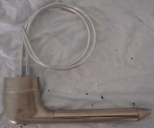
As I wait for my wing kit to arrive, I’ve been purchasing items that will be needed to complete the wings. My most recent purchase is a Dynon pitot/AOA probe to complete my pitot-static system.
For the non-aviation geeks, the pitot-static system is a two part system that is used to measure airspeed and altitude. The system itself is very simple, consisting of ports on the outside of the plane which are connected to tubing. The tubing then runs to various instruments. The instruments translate changes in air pressure to useful information.
The pitot tube, mounted under the wing in this case, is used to measure airspeed. The static ports, consisting of two ports on the aft fuselage, are used to measure altitude and help correct the airspeed. Both the pitot and static ports allow outside air to enter the tubing they are attached to. The static ports are out of the slipstream and allow static air to enter. The pitot tube points forward. Air is forced into the tube as a result of the airplanes forward motion. The faster you go, the higher the pressure will be in the pitot system. The tubing for the pitot-static system is routed to various instruments which measure the pressure in the system and convert that to useful information such as airspeed and altitude. It may sound complicated, but it is actually a very simple system.
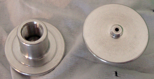
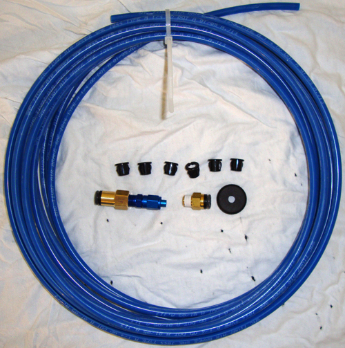
Van’s supplies aluminum tubing in the kit. This tubing is used to make all the pitot-static lines and the pitot tube. The static ports supplied in the kit are nothing more than a couple pop-rivet heads with tubing glued on to the back. While this works perfectly well, I decided to go another route. I’m using the Safeair1 pitot-static and AOA tubing kits, the Safeair1 pitot mast, the Safeair1 static ports, and a Dynon pitot/AOA tube.
The Safeair1 pitot, static, and AOA tubing is plastic tubing and push-on connectors. I feel this will be much easier to install than aluminum tubing and produce fewer leaks that have to be tracked down and fixed. The Safeair1 static ports are billet aluminum that has been milled to duplicate the shape of the Van’s pop-rivet port. They won’t work any better than the Van’s method, but they just look nicer.
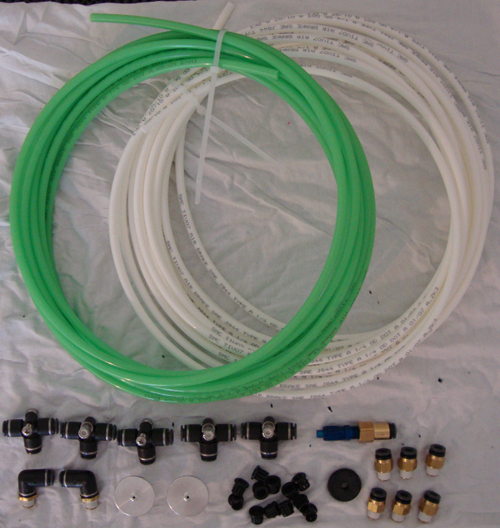
The Safeair1 pitot-static tubing kit contains everything needed for an RV pitot-static system except for the pitot tube.
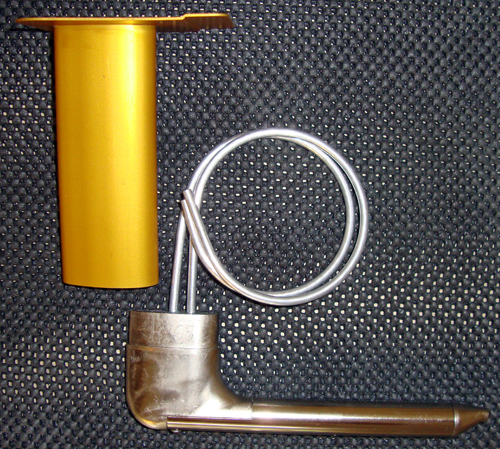
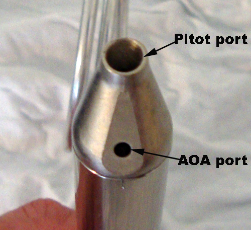
The only reason I’m using the Safeair1 pitot mast is because it is specifically made for use in an RV with the Dynon pitot/AOA tube. This alone should make it simple to install. The Dynon pitot/AOA is basically two tubes wrapped up in a very nice package. The upper port is the pitot port, while the lower port is the AOA. The AOA (or Angle of Attack) uses differential pressure between the two ports to measure the wing’s angle of attack (wing chord vs. relative wind). Simply put, it is a type of stall warning. However, AOA can also be used as a tool for landing. Navy pilots fly AOA, not airspeed, when they land on carriers.
My First Wing Component Arrived (3/26/10)
Posted by Ethan Jacoby in Construction, Wings on March 28, 2010

Since we both had colds, my girlfriend and I stayed in for my birthday. She still made me dinner and some cupcakes though!
Today is my birthday and I received my first wing component! My girlfriend gave me a Safeair1 pitot mast…how did she know that was what I wanted? OK, maybe I sent her a link to the Avery Tools webpage where they are sold.
Eventually, I’m planning to use a Dynon AOA pitot probe. The Safeair1 mast was designed for RVs and the Dynon probe, but it will fit others as well. Van’s supplies aluminum tubing to make a pitot probe from, but I just don’t like the way this looks. Many people say it is very easy to bump into the probe and bend it as well. The Dynon probe just looks better and it will also feed AOA information to whichever EFIS I choose to use (Dynon or MGL).


