Posts Tagged fuel vent
Vent Lines and Random Stuff (2/16/13)
Posted by Ethan Jacoby in Center Fuselage, Construction, Forward Fuselage, Fuselage on February 16, 2013
4.0 Hours –
I didn’t think I had spent four hours in the garage. I didn’t accomplish much, but, before I knew it, it was starting to get dark outside.
My order from JDair.com had arrived, so I was able to go back to work on the vent lines. The JDair fuel vents are much nicer than I thought they would be, consisting of a flared tube fitting and a machined aluminum vent. The vents also have small pieces of screen in the openings to prevent anything from getting in. Although the Van’s method of grinding a tube fitting to a 45 degree angle works, the JDair vents just look nicer. Granted, no one will probably ever notice them on the bottom of the plane.

The JDair.com fuel vents. Much nicer than the Van’s method of grinding the lower portion of an AN fitting.

Another view of the JDair fuel vents. I really like these!
The vents were easy to install since they simply screw onto the fitting. The vent lines were another matter. The shape of my vent lines was good, but getting the cushion clamps, which hold the lines to the top forward gussets, fastened was challenging since these locations used stop nuts instead of platenuts. Normally, this isn’t an issue, but holding the clamp closed and trying to get the nut started, all in an area that you can’t really see, made it a bit difficult. Eventually, the vents were fully installed and I tightened the fittings.

The left vent line installed in the cabin.
I had been contemplating the purchase of an aftermarket tailwheel fork as well. Since I was ordering the fuel vents from JDair, I decided to order their tailwheel fork too. Again, the construction is very nice. The biggest difference between this fork and the Van’s fork is ground clearance. The Van’s fork is parallel to the ground, while the JDair fork is at a 45+ degree angle to the ground. While I’ll probably fly mainly out of paved fields, the increased clearance will be there if I need it.

My new tailwheel fork from JDair.com. I spent a few extra bucks and got the powder coated version.

The JDair fork (black) has much more ground clearance than the Van’s fork. Construction also seems a little more robust.
With the new fork in hand, I spend a few minutes swapping the Van’s fork out on the tailwheel spring. I also switched out the Van’s steering arm with the single-sided steering arm since I’ll eventually be using the JDair tailwheel link instead of the springs from Van’s. Finally, I went ahead and installed the tailwheel in the fork…why not…it’s just been sitting under my workbench collecting dust.

The completed tailwheel assembly.
I’m still going back and forth on whether to mate the wings now or later. I took some measurements in our garage, and I don’t think there is anyway the plane can fit in the garage with both wings on and the door closed. However, an option would be to mate the wings in the driveway, get the aft spars drilled, then take one wing off and move the plane back inside. The rest of the finishing work could be done one wing at a time. Alternatively, the rest of the wing work could wait until I’m in a hangar and space isn’t a concern. In any case, I decided to take my 7/16″ hardware store bolts and convert them into drift pins by grinding off the threads. It took about a half hour to get four made, but at least I have them ready if I decide to install the wings.
Next, I did the finishing work on the flap actuator covers. These are made from really thin aluminum, so I really had to be careful with the Scotchbrite wheel. Later, I primed and painted these along with the forward seat floors.

More painting. These are the forward seat floors and the flap actuator covers.
The next random task was to rivet the rudder pedal center brace to the firewall. I don’t think this is going to be in the way anymore, so I decided to go ahead and rivet it. Fortunately, all 5 rivets could be reached with my squeezer.

The center rudder brace is riveted to the vertical firewall angle. Hopefully this won’t be in my way.
Finally, I did a couple of really random tasks. I installed the elevator pushrod, just to get it off the floor, and I installed the seat backs. The seat back installation actually had a purpose. I wanted to make sure the spacing was correct before riveting the bottom hinge on the seat back. Many people have interference issues with the seat backs on the canopy deck due to some confusing dimensions in the plans. I didn’t think I made this mistake, but I held off riveting the bottom hinge until I could confirm it. Plenty of room and no interference, so I’ll rivet the hinge soon.

Just for fun, I threw the seats in. The fit is perfect.
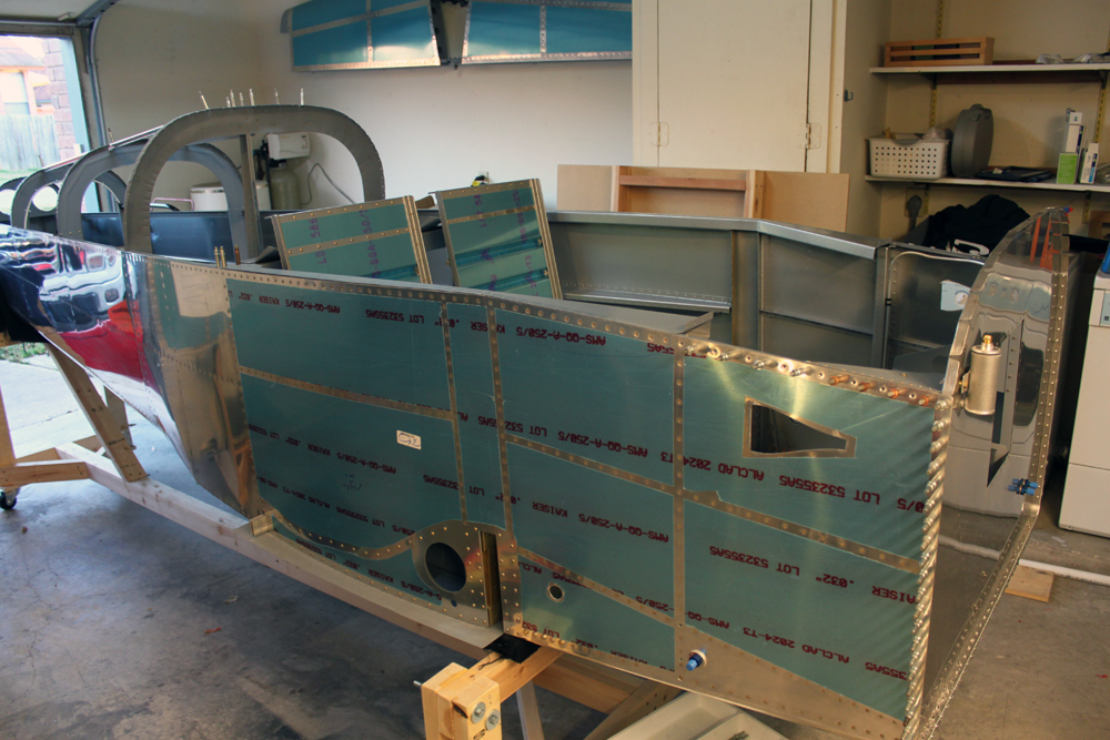
Another view of the fuselage with the seats installed.
F-782D Angles, Brake Reservoir, and Vent Lines Installed (2/9/13)
Posted by Ethan Jacoby in Construction, Forward Fuselage, Fuselage on February 9, 2013
5.0 Hours –
With most of the fabrication finished on the F-782D angles, it was time to drill them to the fuselage. It sounds simple, but it isn’t. The problem is that there are really no guides for the placement of these angles, there’s no way to clamp the angles to the fuselage, and you only drill through the F-7101 and not the side skin…drill too far, and you end up with some new holes that shouldn’t be in the outer skin! As usual, however, this turned out to be easier than I thought it would be.
In order to locate the correct position of the angles, I temporarily installed the F-782A cover plates. The position of plates determines the angle of the angles (wait…what?). Once the cover plates were installed, I simply used the edge of the plates to draw a line on the side of the fuselage that indicated the final angle and position of the plate. The F-782D angles are installed to match this line. To hold the angles in place while I drilled them, I used a short piece of double-sided tape and stuck them to the fuselage. This actually worked very well, except I had trouble removing the tape from the left side. Once stuck in place, I drilled the angles to the F-7101 gear web using a #30 drill with a drill stop placed slightly over 1/8″ from the tip.
After drilling the angles, I removed the double-sided tape and re-clecoed the angles to the fuselage. The cover plates were also re-positioned so I could mark the location of the fuel line cutout on the angles and check to make sure I would have enough edge distance on two screw holes I had to drill. Everything came off once again, and I cut the fuel line openings and drilled two #40 holes in the cover plates. Everything went back on, and I match-drilled the two new holes through to the angles and then enlarged the holes to #19 for #8 screws.

After drilling the F-782D angle to the fuselage, I positioned the F-782A cover to in order to determine how far inboard to drill holes for the screws.
Once final prep was finished on the angles, it was time to rivet them to the fuselage. The plans call for LP4-3 blind rivets. As many others have noted, these rivets are really too long for the application, but they can be installed by slowly pulling and pressing down. Instead, I opted to use some shorter rivets I had on hand from my fuel tank fix. The AD-42-H rivets I used have almost the same grip as the LP4-3 rivets, but, since they are closed end, they don’t have a shank extending past the end, adding to their overall length. With these rivets, installation was easy and all the rivet heads are sitting flush. After the angles were riveted t the fuselage, I had to rivet on the two platenuts. It would have been easier to rivet the platenuts first, but then I would have had access blocked to at least one blind rivet. Eventually, however, I managed to figure out how to get my squeezer to all of the platenut rivets.

The plans called for LP4-3 (right) rivets to install the F-782D angles. However, they are way too long. Instead, I used AD-42-H (left) since they were the only rivets I had on hand that were a bit shorter.

The right F-782D after riveting it to the fuselage.

Another view of the F-782D after riveting.
Looking at my remaining parts, I decided to do something easy next…install the brake fluid reservoir. The reservoir is bolted to the upper right side of the firewall, using the upper firewall angle as a doubler. This was pretty much a matter of finding the correct position, drilling the bolt holes, and then figuring out where to drill a larger hole for where the reservoir passes through the firewall. Deburring the stainless steel firewall took more time than anything else. I also installed the firewall fittings for the brake lines. When I’m ready to install the actual brake lines, I’ll use some firewall sealant to seal up the gaps on the reservoir pass through.

The brake fluid reservoir installed on the firewall.

A closer view of the front of the brake fluid reservoir.

The back side of the brake fluid reservoir.

I installed the brake line fittings on the firewall. Eventually, these will connect the brake pedals to the lines that run to the wheels.

The cabin side of the brake line fittings.
The last thing I did was to fabricate the cabin portion of the fuel vent lines. The vent lines supply positive pressure to the fuel tanks, and they have to be long in order to accommodate expansion of fuel in the tanks when the tanks are full. If expansion becomes too great, fuel will get dumped overboard. Some use a coiled length of tubing in the wing root, but I decided to stick to the plans and have the lines run into the cabin. Once the lines enter the fuselage from the wing, the travel up the forward fuselage bulkhead, then along the longeron, then back down the corner of the firewall/fuselage until they exit through the floor.
I started on the right side and it was a real pain to get all the curves formed. The initial curves are the toughest since the tubing has to make 4 small curves right after entering the fuselage. At this location, it has to curve to get around an angle, then curve the other way to stay clear of the rudder cable. Eventually, I had the tubing formed by using some, not so gentle, bending technique and clamping the tubing in position as I progressed. The left side went more quickly, and looks better than the right, but I’m OK with how they turned out.
Once the vent lines were bent, I installed the end fittings. My Rolo-Flair sure makes easy work of flaring the tube ends. I haven’t installed the lines on the fuselage yet, however, as I want to order the nicer fuel vents from JDair.com, rather than using the modified AN fittings as laid out in the plans. It will be easier to install everything at once so that I can adjust the fit as needed.

The outer portion of the fuel vent line fitting. The vent line will transition from the wing to the fuselage here.

The cabin side of the fuel vent line fitting.

It took some work, but eventually I configured the right fuel vent line.

This was the tricky part of the vent line. Right after it enters the fuselage, it needs four small curves to clear the angle and rudder cable.


Interesting Stuff


